Tutorial - AutoCAD
Level: Intermediate
Time: 30–45 min
Prerequisites:
- You have a VIKTOR account and completed the installation process. No account? Get one here
- You have AutoCAD installed and licensed on a Windows computer.
- You can install VIKTOR Desktop on that computer and open a drawing in AutoCAD.

Introduction
Welcome to this tutorial on how to create VIKTOR apps that draw directly in AutoCAD.
If you create structural drawings, many details follow the same rules but change from one project to another. Beam dimensions, reinforcement, bay spacing, storey heights, and member sizes may all change. Here you can choose between three App Builder prompts and a step-by-step local development example. Both paths draw in the AutoCAD file already open on your computer.
Start with VIKTOR Desktop and the AutoCAD worker, then choose a tab in Choose your approach. The Prompt guide offers three workflows:
- Draw a reinforced-concrete beam detail.
- Draw a structural-steel stair detail.
- Create a parametric 3D structural frame.
If you're comfortable with Python and want to build the app yourself, select the Local development tab under Choose your approach. You'll build a simple beam-detail app step by step. Complete the AutoCAD and VIKTOR Desktop setup below first, as it applies to both approaches.
1. Set up AutoCAD and VIKTOR Desktop
Both approaches use a personal worker to connect a VIKTOR app to AutoCAD on your Windows computer. First, check the VIKTOR Desktop requirements, then download and install VIKTOR Desktop and log in with your VIKTOR account.
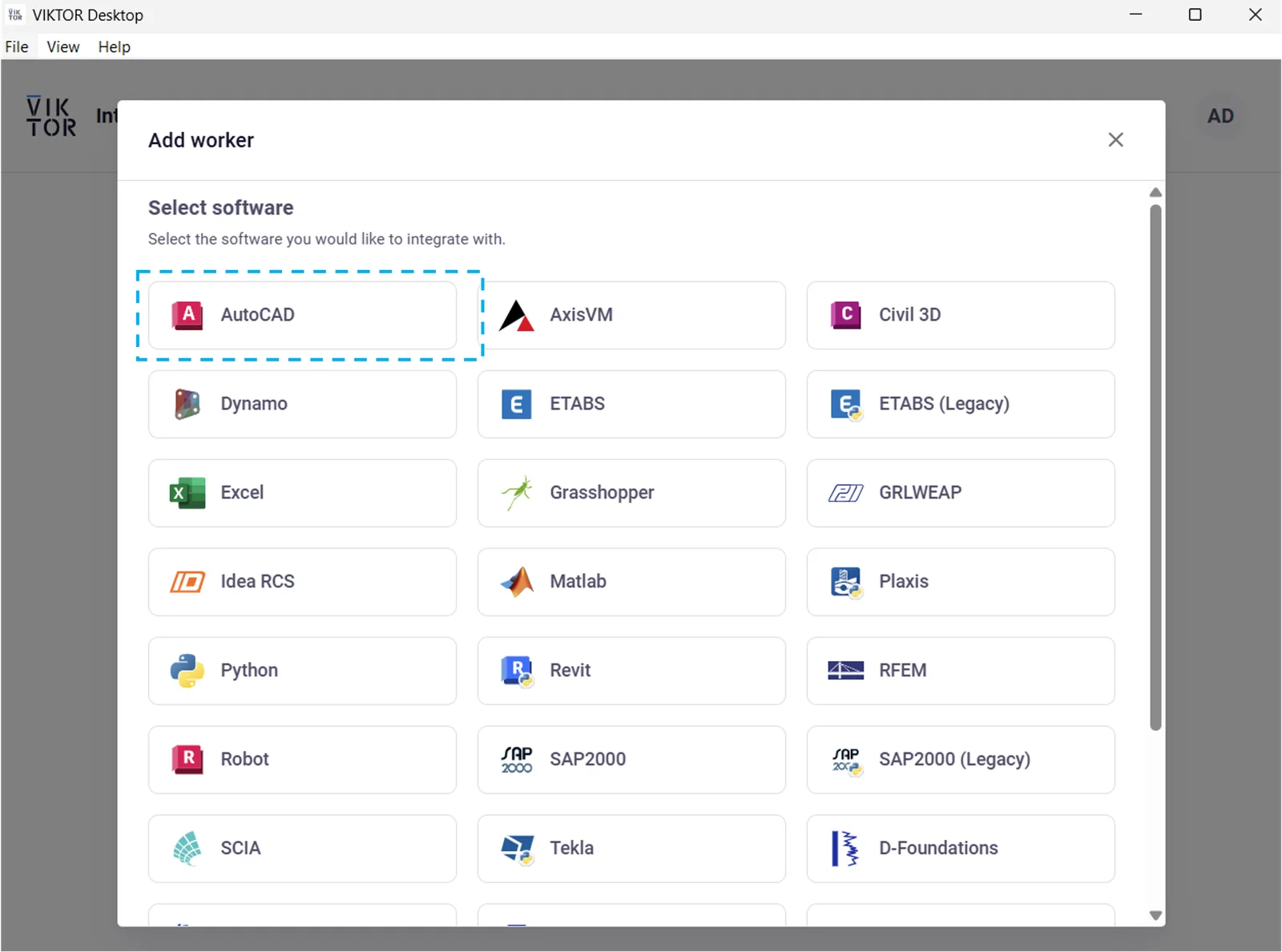
In VIKTOR Desktop, click Add, choose AutoCAD, and start the worker. The worker and AutoCAD must run on the same computer and under the same Windows user. Follow the AutoCAD worker installation steps if you need more detail. You do not need to install Python on the worker computer.
Select AutoCAD in the Add worker window:
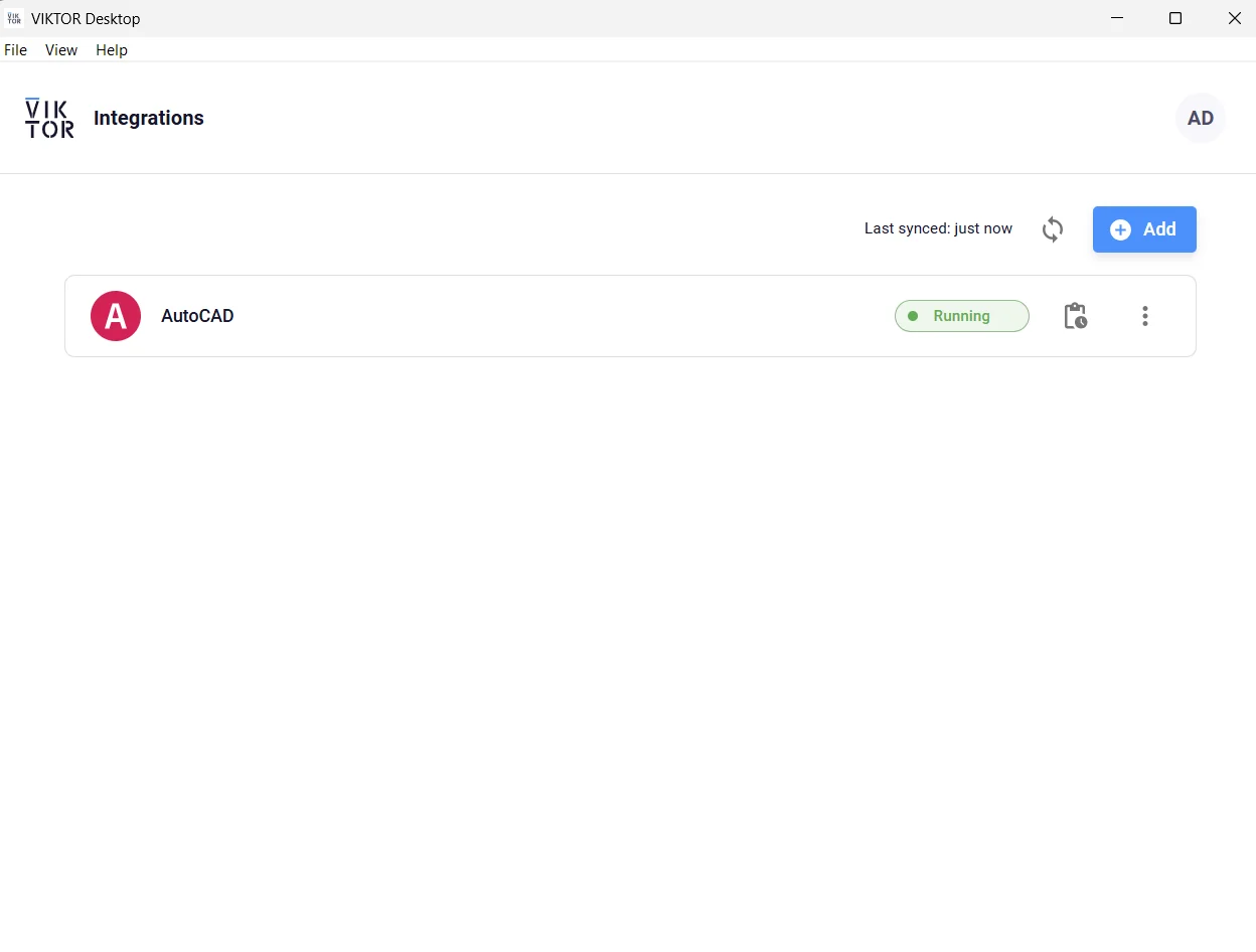
After starting the worker, check that its status is Running:
Before running either app:
- Open AutoCAD on the computer where the personal worker is running.
- Open the drawing you want the app to update.
- Check that the AutoCAD worker is running in VIKTOR Desktop.
- Keep AutoCAD free of open dialogs, then trigger the drawing action from the VIKTOR app.
AutoCAD needs a logged-in Windows desktop session. The worker cannot attach to AutoCAD if the application is closed or waiting on a dialog.
2. Understand the key concepts
Although you can get quite far with a clear prompt, it helps to understand how the app reaches AutoCAD:
- Personal worker: a small program managed through VIKTOR Desktop. It passes drawing operations from the VIKTOR app to AutoCAD on your own computer.
vkt.autocad.attach(): connects the app to the AutoCAD instance that is already open. It does not start AutoCAD or create a separate drawing. Read more in Attaching to a running instance.- Active drawing: the drawing currently open in AutoCAD. The generated app adds geometry to this drawing, so start with the correct file and save it yourself when the result is ready.
- AutoCAD ActiveX API: the set of drawing operations used by the app. It can create lines, polylines, dimensions, blocks, layers, and 3D solids without sending commands to the AutoCAD command line.
- Layers: named groups that keep concrete, reinforcement, dimensions, annotations, or 3D objects separate. A clear layer prefix makes generated content easier to review, hide, or remove.
- Regeneration: refreshing the drawing after the app finishes. Regenerating once at the end is faster than refreshing after every object is added.
You can also use vkt.autocad.connect() to start a new AutoCAD instance, do the work, and close it when the session ends. This tutorial uses attach() to keep the drawing open so you can review and save it yourself. Both methods are BETA and require viktor >= 14.35.0.
3. Choose your approach
Use the Prompt guide to generate an app with the VIKTOR App Builder, or Local development to build a small beam-detail app yourself. The Desktop and worker setup above applies to both tabs.
- Prompt guide
- Local development
Explore AutoCAD workflows with prompts
The following prompts help you turn common AutoCAD drawing tasks into interactive VIKTOR apps. Use the arrow on each prompt to open it in the App Builder, then adapt it to your needs. Once the app is generated, review its inputs and code before running it against your open drawing.
Prompt 1: Draw a reinforced-concrete beam detail
Let's start with a reinforced-concrete beam detail. It is useful when the same drawing standard must be applied to beams with different spans, sections, reinforcement, and clear cover. The app creates an elevation and cross-section from your inputs.



Reinforced-concrete beam detail
Once the App Builder finishes creating the app, check the default beam dimensions and reinforcement values. Open a copy of your AutoCAD drawing, run the action, and confirm that the elevation, cross-section, dimensions, and annotations use the expected scale and layers. Here is the generated app and its beam detail:
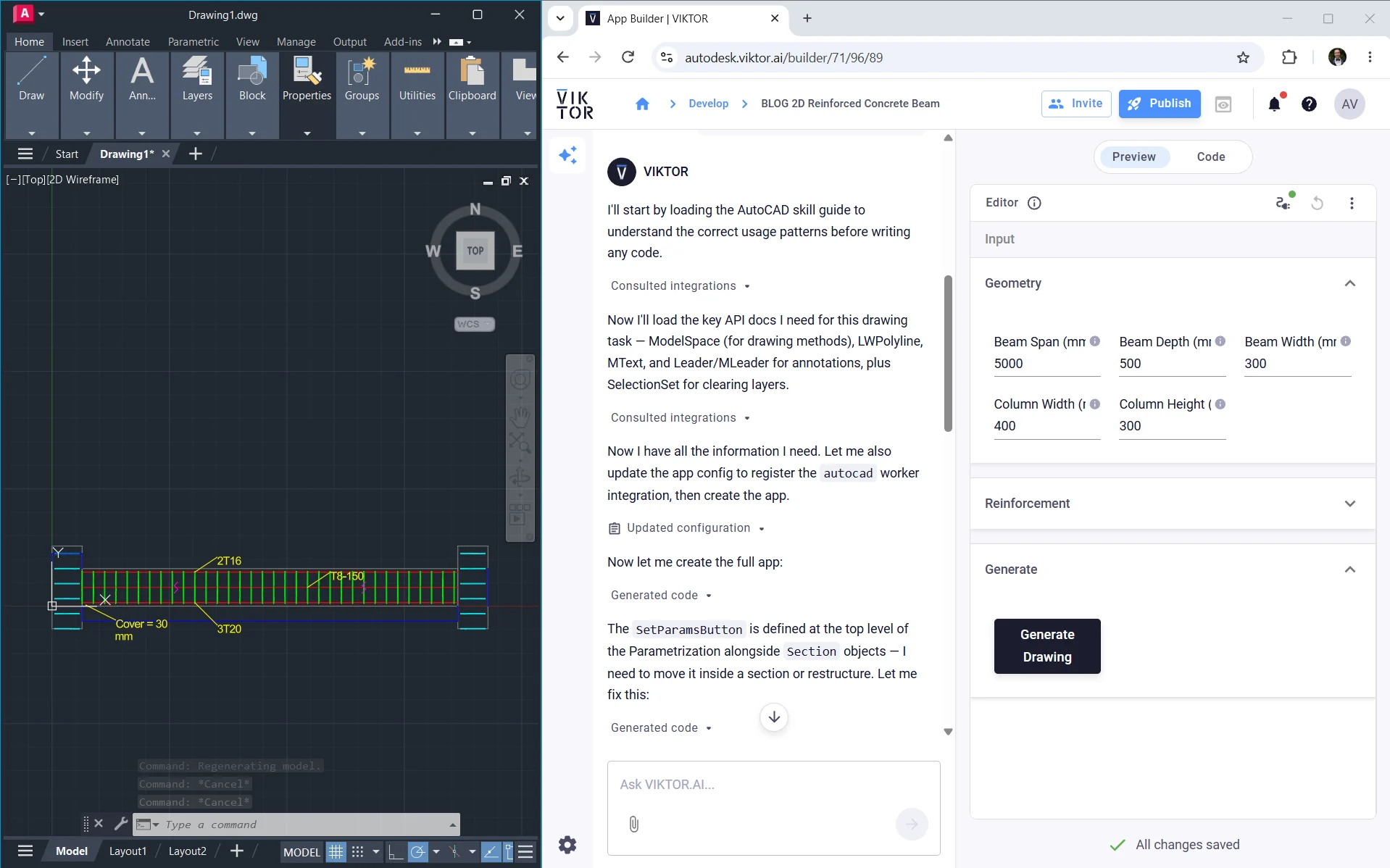
Ask the App Builder to add your office layer names, colors, text style, dimension style, and bar-mark format. This turns the general example into a detail that follows your drawing standard.
Prompt 2: Draw a structural-steel stair detail
The second workflow draws a steel stair in several coordinated views. It is useful when a stair's floor height, width, or riser count changes, but you still need consistent geometry and connection details.
Structural-steel stair detail
Once the app is ready, enter the stair dimensions and create the drawing in a test file. Check that the elevation, plan, tread section, and landing connection agree with the inputs. This example shows the generated VIKTOR app beside the AutoCAD drawing:
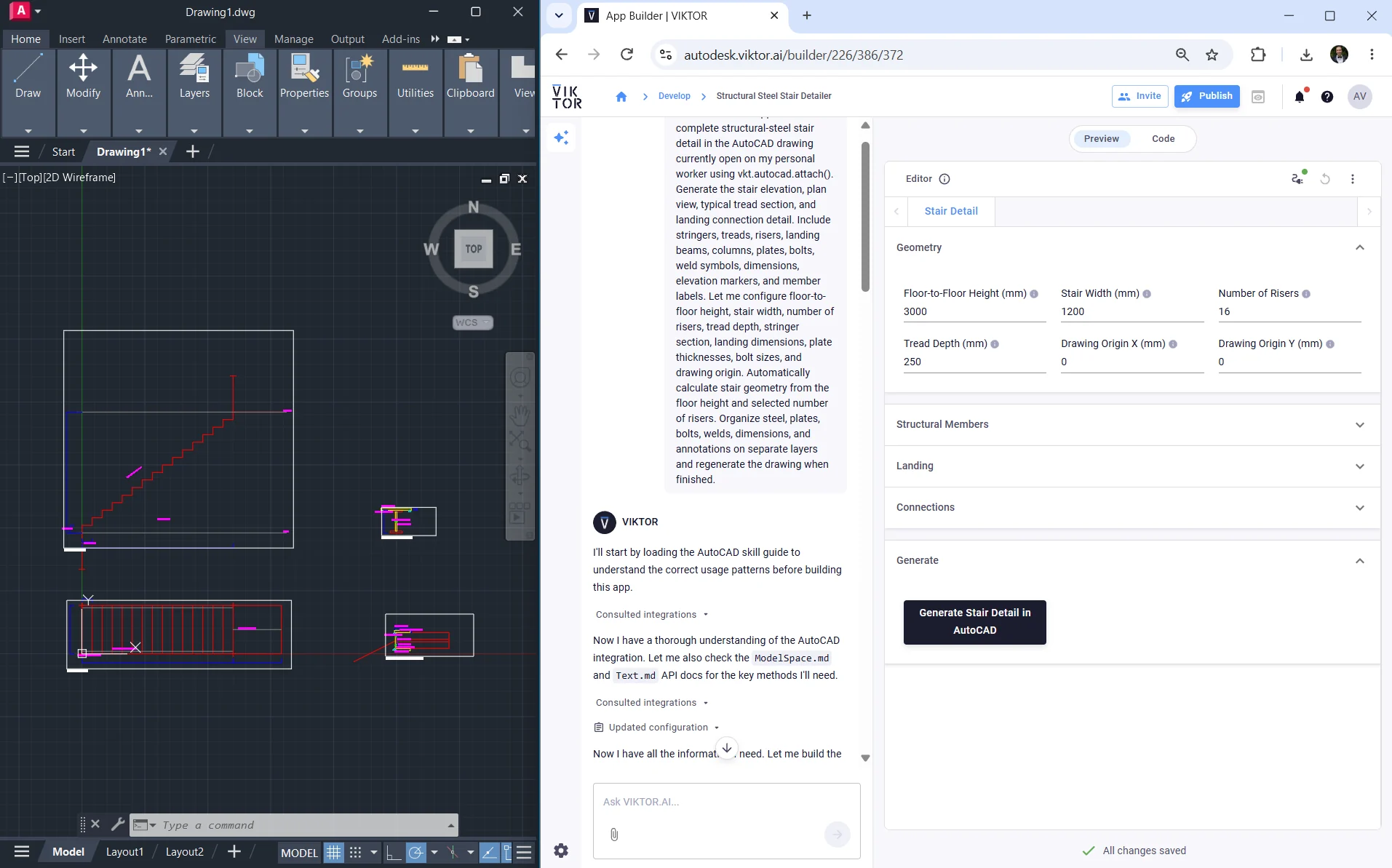
You can extend the prompt with your standard steel sections, connection preferences, and drawing scale. Review the generated plate, bolt, and weld details against your project requirements before using them in a design.
Prompt 3: Create a parametric 3D structural frame
The third workflow creates a 3D structural frame. This is useful for early design studies, when you want to compare bay layouts or member sizes and see the result in AutoCAD without rebuilding every part by hand.
Parametric 3D structural frame
After the app is generated, choose a layer prefix that does not conflict with the existing drawing. Change the frame inputs, run the drawing action, and inspect the columns, beams, and slab in a 3D AutoCAD view. Here is the generated app beside the frame it drew in AutoCAD:
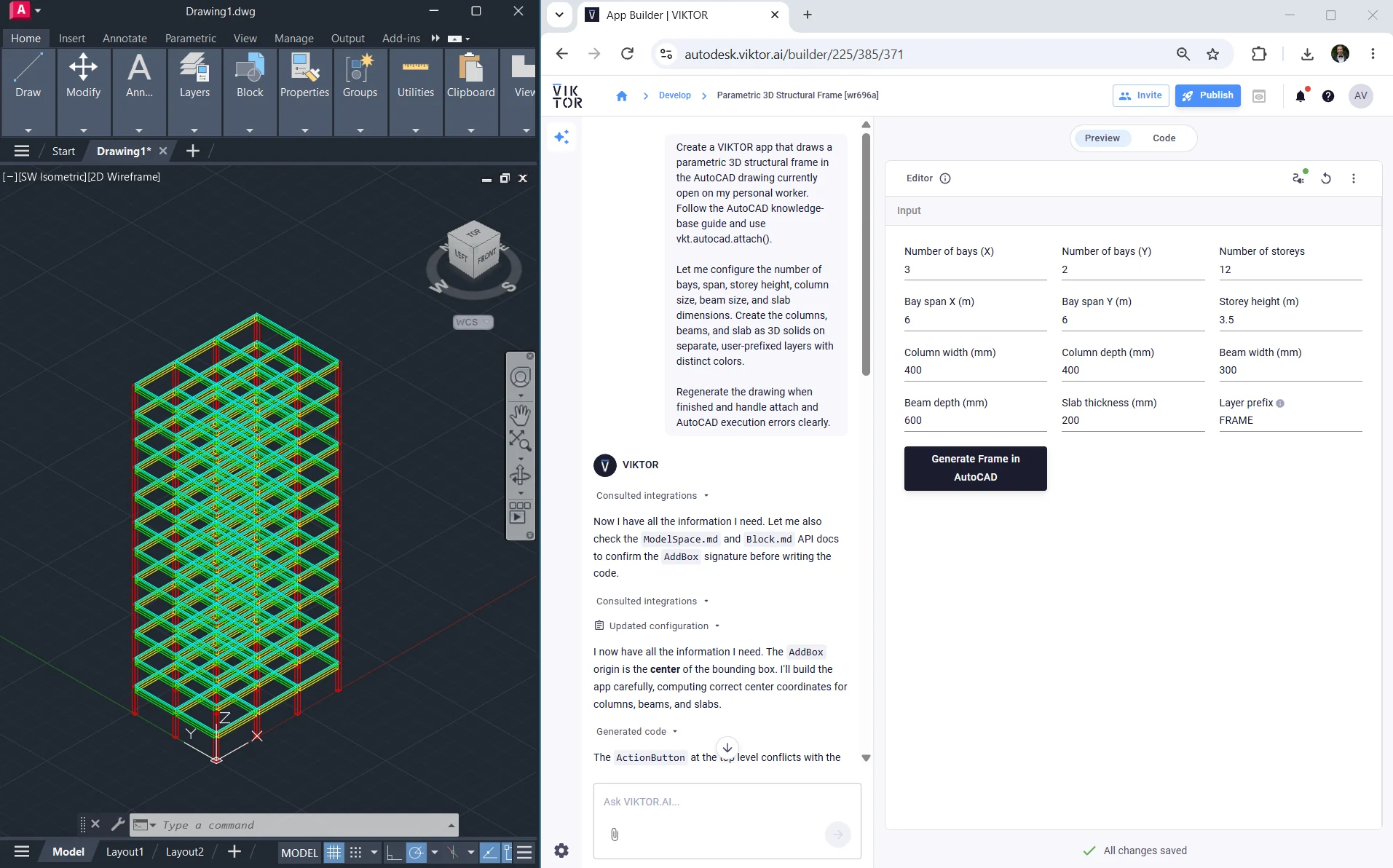
Extend the prompt with grid labels, base plates, foundations, or a choice between replacing the previous result and drawing a new option. A replace option is especially useful when you want to compare several frame configurations without leaving old solids behind.
Create a new VIKTOR app
Want to dive straight into the code? Jump to the complete app.py. You can come back to the steps below when you're ready to build it yourself.
Let's build one small app that draws a reinforced-concrete beam. We will enter a few dimensions in VIKTOR, click a button, and see an elevation and cross-section appear in the AutoCAD drawing that is already open.
First, install the VIKTOR CLI if you have not done so. Then create an editor app from a terminal:
viktor-cli create-app "AutoCAD beam detail tutorial" --init --app-type editor
Open the new app folder in your code editor. Keep that terminal available, as we will start the app after adding the code. The CLI can run on your development computer; the personal worker runs on the Windows computer with AutoCAD.
Configure the VIKTOR app
Open viktor.config.toml and add the AutoCAD worker integration. Keep the registered_name that the CLI generated for your app:
app_type = "editor"
python_version = "3.12"
registered_name = "<your-generated-registered-name>"
worker_integrations = ["autocad"]
In requirements.txt, use a VIKTOR version that supports vkt.autocad.attach():
viktor>=14.35.0,<15
You do not need to install an AutoCAD Python package. The app talks to AutoCAD through the personal worker.
Add the beam inputs
Replace the generated app.py with the example below, one step at a time. Start with a title, six simple inputs, and one button:
import viktor as vkt


class Parametrization(vkt.Parametrization):
    intro = vkt.Text("# AutoCAD Beam Detail Tutorial")
    span = vkt.NumberField("Beam span", default=6000, suffix="mm", min=1000)
    width = vkt.NumberField("Beam width", default=300, suffix="mm", min=100)
    depth = vkt.NumberField("Beam depth", default=600, suffix="mm", min=100)
    cover = vkt.NumberField("Concrete cover", default=40, suffix="mm", min=10)
    bar_diameter = vkt.NumberField("Bar diameter", default=16, suffix="mm", min=6)
    stirrup_spacing = vkt.NumberField("Stirrup spacing", default=200, suffix="mm", min=50)
    draw = vkt.ActionButton("Draw beam in AutoCAD", method="draw_beam", longpoll=True)
All dimensions are in millimetres. The button calls draw_beam when you are ready. It does not draw automatically whenever an input changes.
Draw the beam detail
Add a small helper function below the inputs. AutoCAD expects the coordinates of each corner of a polyline. Setting Closed joins the last corner back to the first one.
class Parametrization(vkt.Parametrization):
    ...


def rectangle(model_space, x, y, width, height, layer):
    points = [x, y, x + width, y, x + width, y + height, x, y + height]
    shape = model_space.AddLightWeightPolyline(points)
    shape.Closed = True
    shape.Layer = layer
Now add the Controller below rectangle in the same app.py. The ... placeholders show code you already wrote, so keep your existing Parametrization and rectangle function. The controller reads the inputs, attaches to the drawing already open in AutoCAD, and creates two layers. Then it draws the elevation and the cross-section. The try block gives a useful message if the worker cannot attach or AutoCAD cannot finish the drawing.
class Parametrization(vkt.Parametrization):
    ...


def rectangle(model_space, x, y, width, height, layer):
    ...


class Controller(vkt.Controller):
    parametrization = Parametrization

    def draw_beam(self, params, **kwargs):
        span = params.span
        width = params.width
        depth = params.depth
        cover = params.cover
        bar_radius = params.bar_diameter / 2
        spacing = int(params.stirrup_spacing)

        if 2 * (cover + params.bar_diameter) >= min(width, depth):
            raise vkt.UserError("Reduce the cover or bar diameter, or increase the beam size.")

        try:
            with vkt.autocad.attach(timeout=120) as acad:
                drawing = acad.ActiveDocument
                model_space = drawing.ModelSpace

                for name, color in [
                    ("VKT-BEAM-CONCRETE", 7),
                    ("VKT-BEAM-REBAR", 1),
                ]:
                    try:
                        layer = drawing.Layers.Item(name)
                    except vkt.errors.ExecutionError:
                        layer = drawing.Layers.Add(name)
                    layer.Color = color

                # Beam elevation and two continuous longitudinal bars.
                rectangle(model_space, 0, 0, span, depth, "VKT-BEAM-CONCRETE")
                for y in (cover + bar_radius, depth - cover - bar_radius):
                    bar = model_space.AddLine([cover, y, 0], [span - cover, y, 0])
                    bar.Layer = "VKT-BEAM-REBAR"

                # Draw one stirrup symbol at each spacing interval.
                for x in range(spacing, int(span), spacing):
                    stirrup = model_space.AddLine(
                        [x, cover, 0], [x, depth - cover, 0]
                    )
                    stirrup.Layer = "VKT-BEAM-REBAR"

                # Add a simple cross-section beside the elevation.
                section_x = span + 500
                rectangle(model_space, section_x, 0, width, depth, "VKT-BEAM-CONCRETE")
                rectangle(
                    model_space, section_x + cover, cover,
                    width - 2 * cover, depth - 2 * cover, "VKT-BEAM-REBAR"
                )
                for x in (section_x + cover + bar_radius,
                          section_x + width - cover - bar_radius):
                    for y in (cover + bar_radius, depth - cover - bar_radius):
                        bar = model_space.AddCircle([x, y, 0], bar_radius)
                        bar.Layer = "VKT-BEAM-REBAR"

                drawing.Regen(vkt.autocad.AcRegenType.acAllViewports)
        except vkt.errors.WorkerSessionAttachError as error:
            raise vkt.UserError(
                "Open AutoCAD and a drawing on your personal worker, then try again."
            ) from error
        except vkt.errors.ExecutionError as error:
            raise vkt.UserError("AutoCAD could not draw the beam. Check the open drawing.") from error
The same dimensions control both views. attach() edits the drawing already on your screen, and Regen() refreshes it once after all objects are added. This is a drawing example, not a structural design check. Verify bar spacing, cover, anchorage, and code requirements before using a detail in a project.
Add labels and a callout
Let's build on the beam and cross-section we just drew. We stay inside the same draw_beam method. The ... lines below stand for code you already have. Add the highlighted annotation layer to the layer list. Then add the highlighted labels and callout after the cross-section's for loops, just before drawing.Regen(...):
class Parametrization(vkt.Parametrization):
    ...


def rectangle(model_space, x, y, width, height, layer):
    ...


class Controller(vkt.Controller):
    parametrization = Parametrization

    def draw_beam(self, params, **kwargs):
        ...
        try:
            with vkt.autocad.attach(timeout=120) as acad:
                ...
                for name, color in [
                    ("VKT-BEAM-CONCRETE", 7),
                    ("VKT-BEAM-REBAR", 1),
                    ("VKT-BEAM-ANNOTATIONS", 2),
                ]:
                    ...

                # Keep the beam elevation and cross-section code here.
                ...

                for label, x in [("BEAM ELEVATION", 0), ("CROSS-SECTION", section_x)]:
                    text = model_space.AddText(label, [x, depth + 180, 0], 80)
                    text.Layer = "VKT-BEAM-ANNOTATIONS"

                note = model_space.AddMText(
                    [span / 3, depth + 420, 0], 1800,
                    f"Stirrups @ {spacing} mm"
                )
                note.Height = 80
                note.Layer = "VKT-BEAM-ANNOTATIONS"
                leader = model_space.AddLeader(
                    [spacing, depth - cover, 0, span / 3, depth + 420, 0],
                    note, vkt.autocad.AcLeaderType.acLineWithArrow
                )
                leader.Layer = "VKT-BEAM-ANNOTATIONS"

                drawing.Regen(vkt.autocad.AcRegenType.acAllViewports)
The two labels name the views. The callout is an AutoCAD leader attached to text, with its arrow pointing to the first stirrup. If you change the spacing input and draw again, the callout uses the new value.
Add a native AutoCAD table
Finally, put the beam inputs in a small schedule below the elevation. Keep everything from the previous step. Add the highlighted table layer as the fourth item in the same list, then insert the highlighted table code after leader.Layer = "VKT-BEAM-ANNOTATIONS" and before the existing drawing.Regen(...). Again, ... stands for unchanged code:
class Parametrization(vkt.Parametrization):
    ...


def rectangle(model_space, x, y, width, height, layer):
    ...


class Controller(vkt.Controller):
    parametrization = Parametrization

    def draw_beam(self, params, **kwargs):
        ...
        try:
            with vkt.autocad.attach(timeout=120) as acad:
                ...
                for name, color in [
                    ("VKT-BEAM-CONCRETE", 7),
                    ("VKT-BEAM-REBAR", 1),
                    ("VKT-BEAM-ANNOTATIONS", 2),
                    ("VKT-BEAM-TABLE", 7),
                ]:
                    ...

                # Keep the beam and annotation code here.
                ...
                leader.Layer = "VKT-BEAM-ANNOTATIONS"
                table = model_space.AddTable([0, -250, 0], 7, 2, 160, 900)
                table.Layer = "VKT-BEAM-TABLE"
                for row_type in (
                    vkt.autocad.AcRowType.acTitleRow,
                    vkt.autocad.AcRowType.acHeaderRow,
                    vkt.autocad.AcRowType.acDataRow,
                ):
                    table.SetTextHeight(row_type, 80)
                table.SetText(0, 0, "BEAM SCHEDULE")
                table.SetText(1, 0, "Parameter")
                table.SetText(1, 1, "Value")
                for row, (name, value) in enumerate([
                    ("Span", f"{span:g} mm"),
                    ("Section", f"{width:g} x {depth:g} mm"),
                    ("Cover", f"{cover:g} mm"),
                    ("Bar diameter", f"{params.bar_diameter:g} mm"),
                    ("Stirrup spacing", f"{spacing} mm"),
                ], start=2):
                    table.SetText(row, 0, name)
                    table.SetText(row, 1, value)

                drawing.Regen(vkt.autocad.AcRegenType.acAllViewports)
AddTable creates an editable AutoCAD table, not a collection of drawn lines. Its rows summarize the same inputs that produced the detail. Leave the one drawing.Regen(...) call at the bottom of the with block, after all geometry, labels, and table cells have been added.
Run the app and check AutoCAD
From the new app folder, run viktor-cli clean-start once. It installs the app dependencies and connects your development app to VIKTOR. Keep the terminal open and use the app link printed by the CLI. Later, use viktor-cli start to reconnect without reinstalling.
Open a copy of a drawing in AutoCAD, check that the personal worker is online in VIKTOR Desktop, and click Draw beam in AutoCAD. The detail, labels, callout, and beam schedule appear on four VKT-BEAM-* layers. Save the drawing in AutoCAD when you are happy with it. Each click adds another detail; the app does not replace the previous one.
The finished app shows the beam inputs beside the elevation, cross-section, callout, and native AutoCAD table:
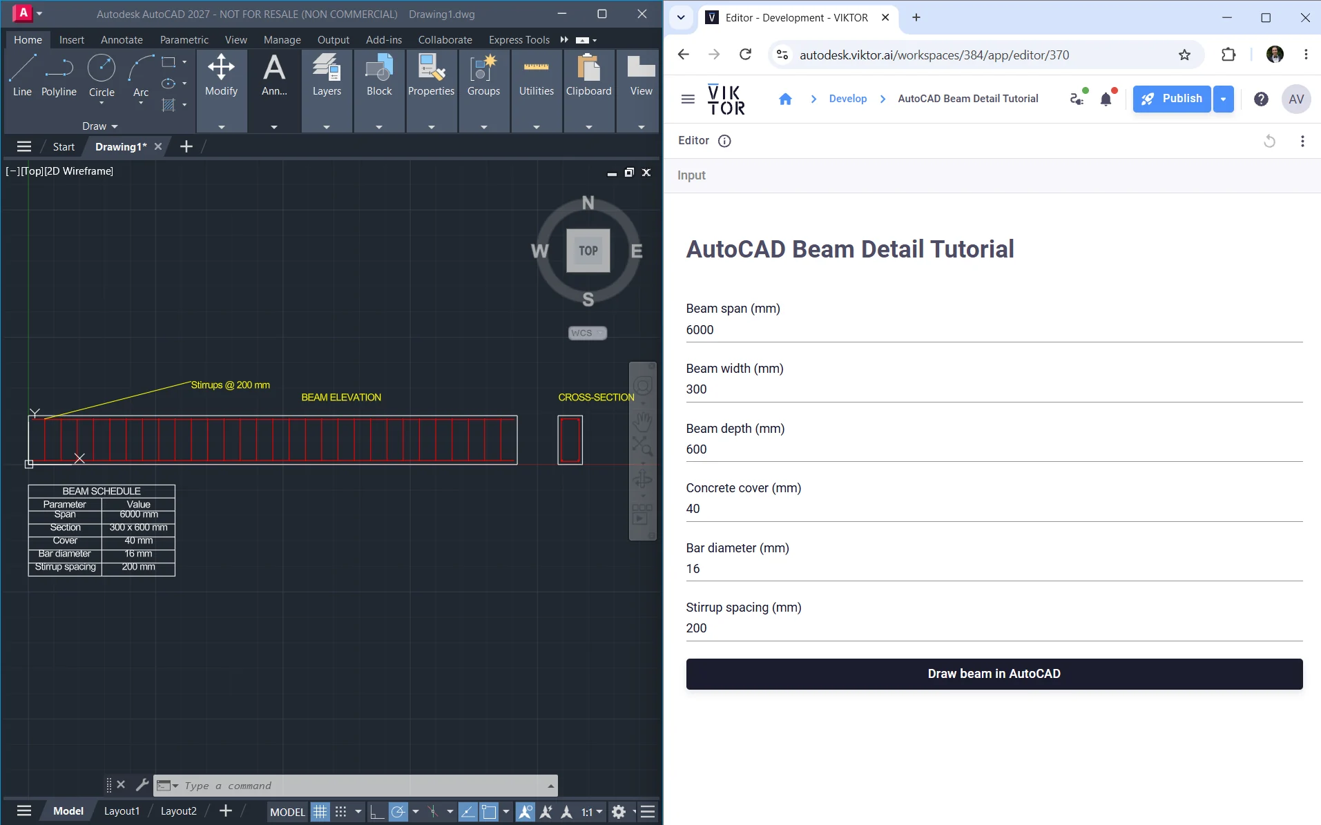
If the app cannot attach, make sure AutoCAD is open on the worker machine and no dialog is blocking it. The AutoCAD integration guide explains the attach errors in more detail.
Complete code
Here is the final app.py with the beam, cross-section, labels, callout, and native table in one place. Open it if you want to compare your code with the finished app.
Complete app.py code
import viktor as vkt


class Parametrization(vkt.Parametrization):
    intro = vkt.Text("# AutoCAD Beam Detail Tutorial")
    span = vkt.NumberField("Beam span", default=6000, suffix="mm", min=1000)
    width = vkt.NumberField("Beam width", default=300, suffix="mm", min=100)
    depth = vkt.NumberField("Beam depth", default=600, suffix="mm", min=100)
    cover = vkt.NumberField("Concrete cover", default=40, suffix="mm", min=10)
    bar_diameter = vkt.NumberField("Bar diameter", default=16, suffix="mm", min=6)
    stirrup_spacing = vkt.NumberField("Stirrup spacing", default=200, suffix="mm", min=50)
    draw = vkt.ActionButton("Draw beam in AutoCAD", method="draw_beam", longpoll=True)


def rectangle(model_space, x, y, width, height, layer):
    """Draw one closed rectangle in the XY plane."""
    points = [x, y, x + width, y, x + width, y + height, x, y + height]
    shape = model_space.AddLightWeightPolyline(points)
    shape.Closed = True
    shape.Layer = layer


class Controller(vkt.Controller):
    parametrization = Parametrization

    def draw_beam(self, params, **kwargs):
        span = params.span
        width = params.width
        depth = params.depth
        cover = params.cover
        bar_radius = params.bar_diameter / 2
        spacing = int(params.stirrup_spacing)

        if 2 * (cover + params.bar_diameter) >= min(width, depth):
            raise vkt.UserError("Reduce the cover or bar diameter, or increase the beam size.")

        try:
            with vkt.autocad.attach(timeout=120) as acad:
                drawing = acad.ActiveDocument
                model_space = drawing.ModelSpace

                for name, color in [
                    ("VKT-BEAM-CONCRETE", 7),
                    ("VKT-BEAM-REBAR", 1),
                    ("VKT-BEAM-ANNOTATIONS", 2),
                    ("VKT-BEAM-TABLE", 7),
                ]:
                    try:
                        layer = drawing.Layers.Item(name)
                    except vkt.errors.ExecutionError:
                        layer = drawing.Layers.Add(name)
                    layer.Color = color

                # Beam elevation and two continuous longitudinal bars.
                rectangle(model_space, 0, 0, span, depth, "VKT-BEAM-CONCRETE")
                for y in (cover + bar_radius, depth - cover - bar_radius):
                    bar = model_space.AddLine([cover, y, 0], [span - cover, y, 0])
                    bar.Layer = "VKT-BEAM-REBAR"

                # Draw one stirrup symbol at each spacing interval.
                for x in range(spacing, int(span), spacing):
                    stirrup = model_space.AddLine(
                        [x, cover, 0], [x, depth - cover, 0]
                    )
                    stirrup.Layer = "VKT-BEAM-REBAR"

                # Add a simple cross-section beside the elevation.
                section_x = span + 500
                rectangle(model_space, section_x, 0, width, depth, "VKT-BEAM-CONCRETE")
                rectangle(
                    model_space, section_x + cover, cover,
                    width - 2 * cover, depth - 2 * cover, "VKT-BEAM-REBAR"
                )
                for x in (section_x + cover + bar_radius,
                          section_x + width - cover - bar_radius):
                    for y in (cover + bar_radius, depth - cover - bar_radius):
                        bar = model_space.AddCircle([x, y, 0], bar_radius)
                        bar.Layer = "VKT-BEAM-REBAR"

                # Label the two views and point a native leader at a stirrup.
                for label, x in [("BEAM ELEVATION", 0), ("CROSS-SECTION", section_x)]:
                    text = model_space.AddText(label, [x, depth + 180, 0], 80)
                    text.Layer = "VKT-BEAM-ANNOTATIONS"

                note = model_space.AddMText(
                    [span / 3, depth + 420, 0], 1800,
                    f"Stirrups @ {spacing} mm"
                )
                note.Height = 80
                note.Layer = "VKT-BEAM-ANNOTATIONS"
                leader = model_space.AddLeader(
                    [spacing, depth - cover, 0, span / 3, depth + 420, 0],
                    note, vkt.autocad.AcLeaderType.acLineWithArrow
                )
                leader.Layer = "VKT-BEAM-ANNOTATIONS"

                # A real AutoCAD table stays editable in the drawing.
                table = model_space.AddTable([0, -250, 0], 7, 2, 160, 900)
                table.Layer = "VKT-BEAM-TABLE"
                for row_type in (
                    vkt.autocad.AcRowType.acTitleRow,
                    vkt.autocad.AcRowType.acHeaderRow,
                    vkt.autocad.AcRowType.acDataRow,
                ):
                    table.SetTextHeight(row_type, 80)
                table.SetText(0, 0, "BEAM SCHEDULE")
                table.SetText(1, 0, "Parameter")
                table.SetText(1, 1, "Value")
                for row, (name, value) in enumerate([
                    ("Span", f"{span:g} mm"),
                    ("Section", f"{width:g} x {depth:g} mm"),
                    ("Cover", f"{cover:g} mm"),
                    ("Bar diameter", f"{params.bar_diameter:g} mm"),
                    ("Stirrup spacing", f"{spacing} mm"),
                ], start=2):
                    table.SetText(row, 0, name)
                    table.SetText(row, 1, value)

                drawing.Regen(vkt.autocad.AcRegenType.acAllViewports)
        except vkt.errors.WorkerSessionAttachError as error:
            raise vkt.UserError(
                "Open AutoCAD and a drawing on your personal worker, then try again."
            ) from error
        except vkt.errors.ExecutionError as error:
            raise vkt.UserError("AutoCAD could not draw the beam. Check the open drawing.") from error
4. Important limitations
The app edits the live drawing through AutoCAD's ActiveX API. Keep these points in mind:
- The app cannot attach when AutoCAD is closed. Open AutoCAD and the correct drawing before running the action.
- The drawing changes are real and are not rolled back automatically. Test the app on a copy of the drawing and use recognizable layer prefixes.
- AutoCAD must remain available. A modal dialog or an active command can prevent the worker from attaching to the running instance.
- The app cannot use interactive command-line prompts. Ask for dimensions and choices in the VIKTOR interface instead of relying on AutoCAD selections or prompts.
- Each AutoCAD operation travels through the worker. Group repeated geometry with polylines, blocks, copies, and arrays, then regenerate once at the end.
For the full list of supported behavior and worker errors, continue with the AutoCAD integration guide.
To infinity and beyond!
Well done! You now have three starting points for creating VIKTOR apps that draw structural details and models in the AutoCAD file open on your computer.
Continue by adapting the prompts to your drawing standards, layer conventions, and engineering checks. You can also explore the Autodesk Forma / ACC tutorial to work with Revit models stored in Autodesk Construction Cloud, or return to the tutorial overview for more examples.