Tutorial - Civil 3D
Level: Intermediate
Time: 30–45 min
Prerequisites:
- You have a VIKTOR account. No account? Get one here.
- You have Civil 3D installed and licensed on a Windows computer.
- You can install VIKTOR Desktop on that computer and open a writable Civil 3D drawing.
Introduction
Welcome to this tutorial on how to create VIKTOR apps that work directly in Civil 3D!
Road geometry often changes during a project. Instead of repeating the same drawing operations, you can describe a workflow in the VIKTOR App Builder, adjust a few inputs, and create native Civil 3D objects in your open drawing. In this tutorial, you will explore three workflows:
- Create a road alignment and set-out points.
- Create an existing-ground longitudinal profile.
- Create three cross sections.
If you're comfortable with Python and want to build the app yourself, select the Local development tab under Choose your approach. You'll build a simple longitudinal-profile app step by step. Complete the Civil 3D and VIKTOR Desktop setup below first, as it applies to both approaches.
1. Set up Civil 3D and VIKTOR Desktop
The apps use a personal worker to connect VIKTOR to Civil 3D on your Windows computer. Check the VIKTOR Desktop requirements, then download and install VIKTOR Desktop and log in with your VIKTOR account.
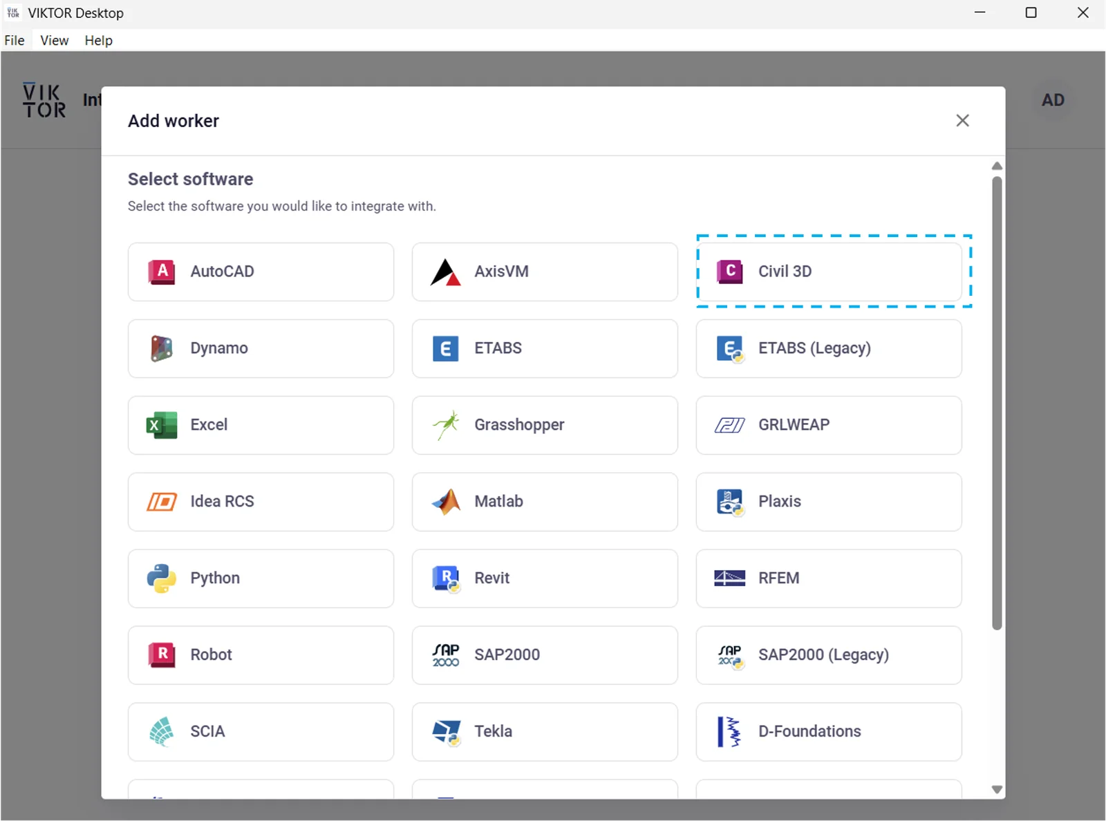
In VIKTOR Desktop, click Add, choose Civil 3D, and start the worker. Follow the Civil 3D worker installation steps for the complete setup. The worker and Civil 3D must run on the same computer, under the same Windows user, in a logged-in desktop session. You do not need to install Python on the worker computer.
Select Civil 3D in the Add worker window:
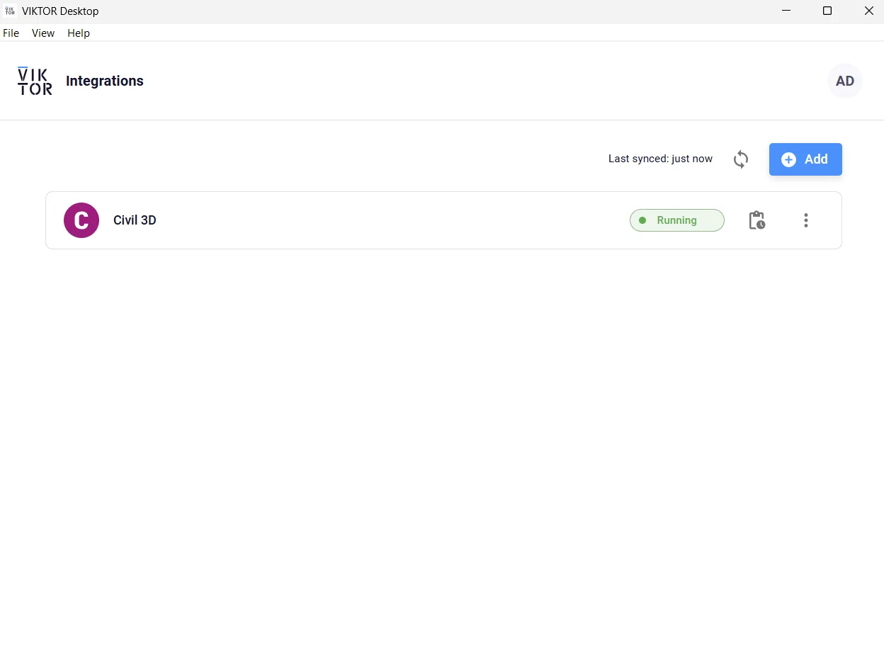
After starting the worker, check that its status is Running:
Before running either app:
- Open Civil 3D and a copy of the drawing you want to work with.
- Use a metric drawing for these examples and set the worker's units to metric.
- Make sure the drawing is writable and Model Space is active.
- Close any dialogs and finish active commands so Civil 3D is idle.
- Check that the Civil 3D worker is running in VIKTOR Desktop.
These apps change the drawing that is already open. Test on a copy, review the result, and save it yourself in Civil 3D. Closing a connection does not undo drawing changes.
2. Understand the key concepts
Although you can get quite far with a clear prompt, a little context helps you choose the right inputs:
- Personal worker: the connection between the VIKTOR app and Civil 3D on your computer. The app uses
vkt.civil3d.attach()to reach the instance that is already open. - Alignment and station: an alignment describes a route in plan. A station is a distance measured along that route, so you can identify where a point or section belongs.
- COGO points: Civil 3D survey points with coordinates and descriptions. Set-out points help locate the route on site. E/N/Z means easting, northing, and elevation.
- PI, PC, and PT: the intersection of two tangents, the start of a circular curve, and the end of that curve.
- Surface and profile: a surface represents terrain. An existing-ground profile shows its elevation along an alignment; a profile view displays that information on a grid.
- Sample lines and cross sections: sample lines cut across an alignment at selected stations. Sections show the sampled terrain to the left and right, and section views display those cuts in the drawing.
- Styles: drawing settings that control how Civil 3D objects and labels look. The profile and cross-section apps inspect your drawing so you can choose styles that already exist.
You can also use vkt.civil3d.connect() to start a new Civil 3D instance, do the work, and close it when the session ends. This tutorial uses attach() to keep the drawing open so you can review and save it yourself. Both methods are BETA and require viktor >= 14.36.0.
3. Choose your approach
Use the Prompt guide to generate an app with the App Builder, or Local development to build a small longitudinal-profile app step by step. Both approaches use the Desktop and worker setup above.
- Prompt guide
- Local development
Explore Civil 3D workflows with prompts
Select the arrow to open a prompt in the VIKTOR App Builder. Review the generated app and its preview before running an action that changes your drawing. The screenshots show example results; your app's layout may differ.
Prompt 1: Create a road alignment and set-out points
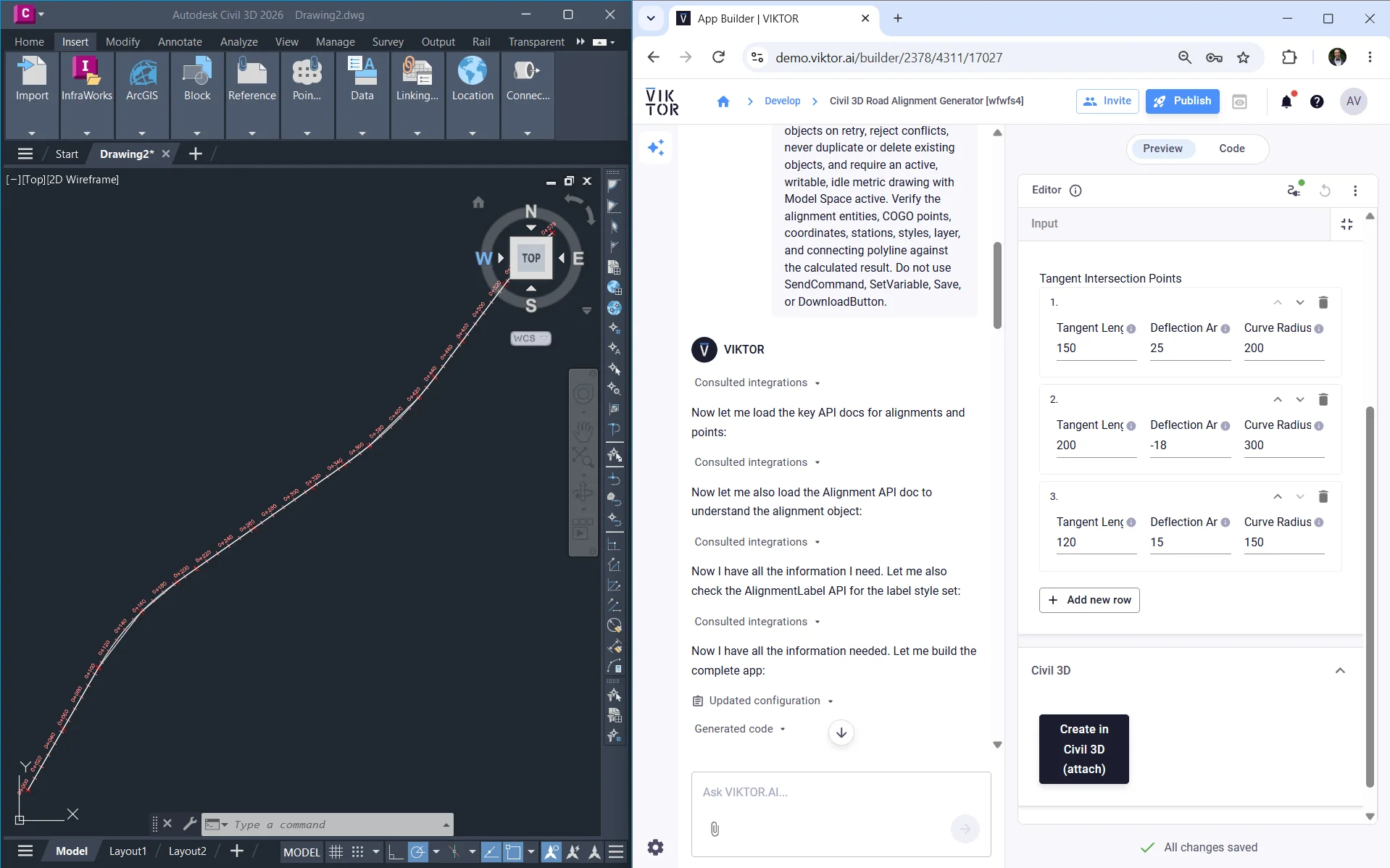
Let's start with a road alignment. This workflow is useful when you want to explore a route from a few geometric inputs and check its set-out coordinates before adding anything to Civil 3D. Enter the starting coordinates, bearing, and tangent and curve values, then review the alignment preview and point table.



Road alignment and set-out points
Once the App Builder finishes, adjust the inputs and inspect the curve geometry and point coordinates in VIKTOR. This lets you catch an unexpected bearing or radius before writing to the drawing.
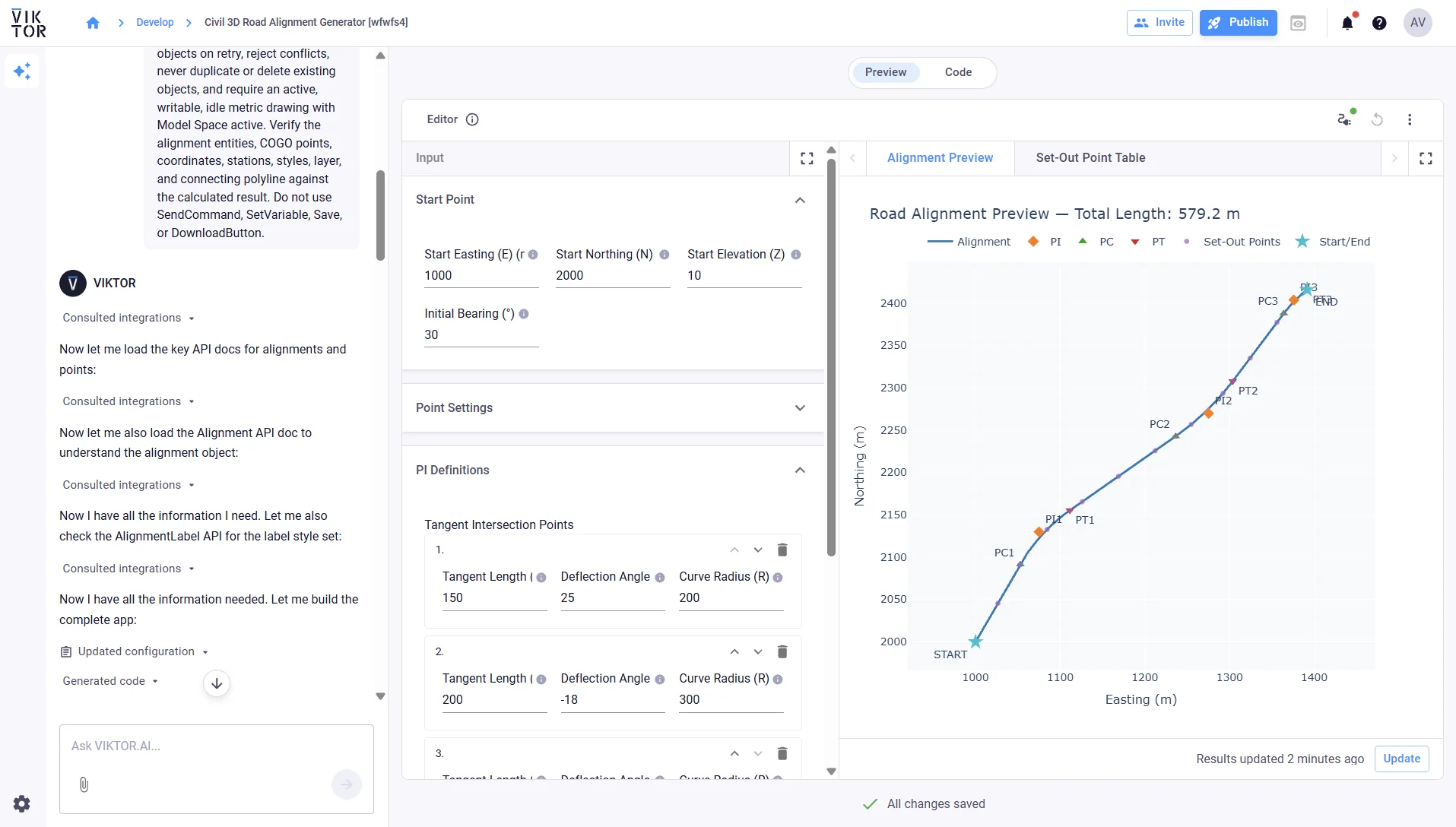
When the preview looks right, run the creation action. In Civil 3D, inspect the native alignment, point labels, and polyline connecting the set-out points. Check the app's verification results before saving the drawing.
Ask the App Builder to add an Excel export of the point table or checks for your project's minimum curve radius. Keep the preview separate from the drawing action so you can compare alternatives before creating objects.
Prepare a drawing for prompts 2 and 3
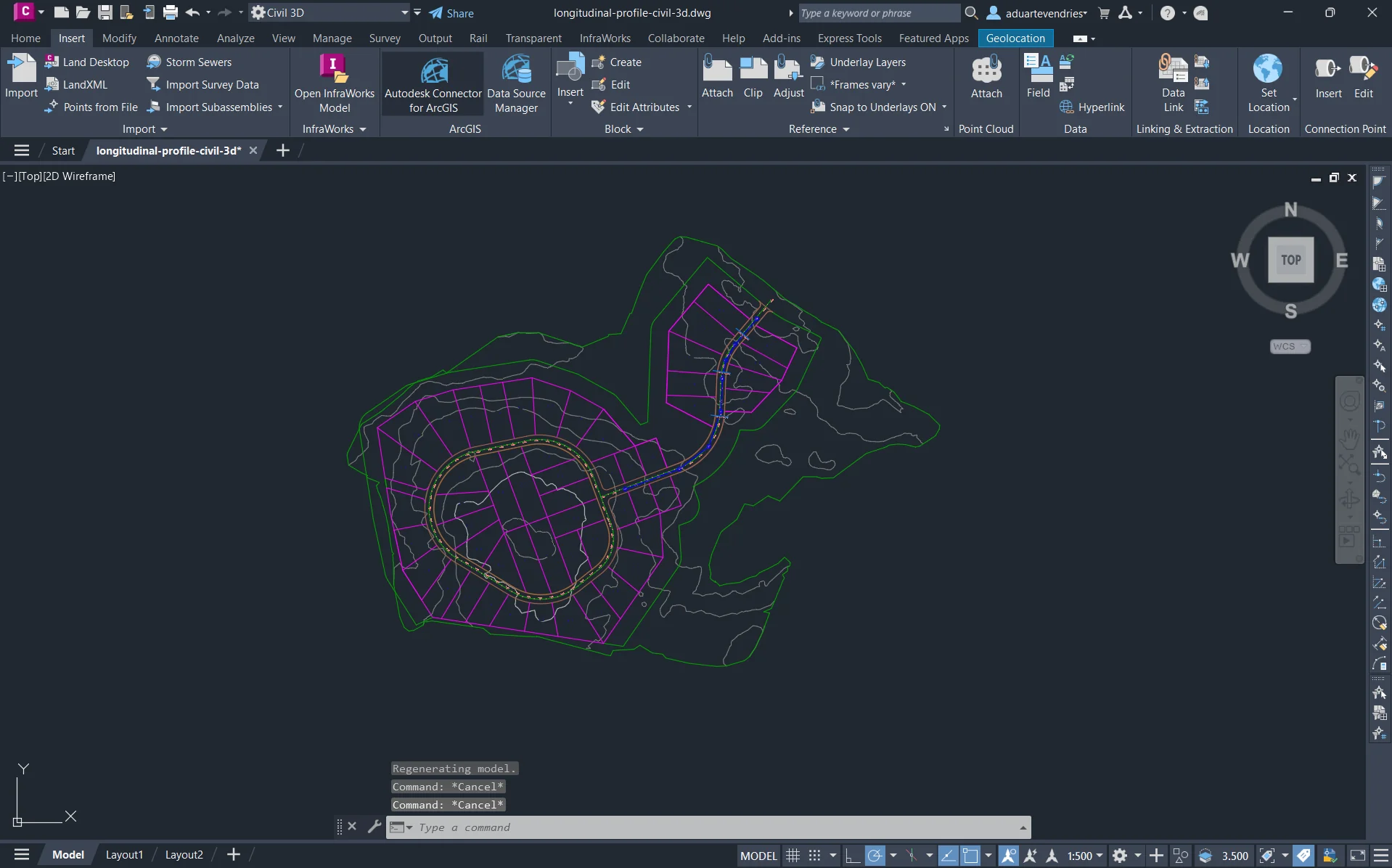
For the next two prompts, download and open the sample Civil 3D drawing in Civil 3D. You can also use your own metric drawing with an existing alignment and a terrain surface covering the stations and sampling widths you want to use. It should contain the profile, sample-line, section, view, group-plot, and band-set styles requested by the apps. Work on a copy and inspect the available objects and styles before creating a result.
The sample drawing contains a road layout and terrain surface. The following apps read those existing objects; you do not need to run prompt 1 first.
Prompt 2: Create an existing-ground longitudinal profile
The second workflow shows how the terrain changes along a road. This is useful for reviewing existing ground levels before developing a vertical design. Instead of entering elevations manually, the app samples an existing surface along your chosen alignment and creates a native dynamic profile and profile view.
Existing-ground longitudinal profile
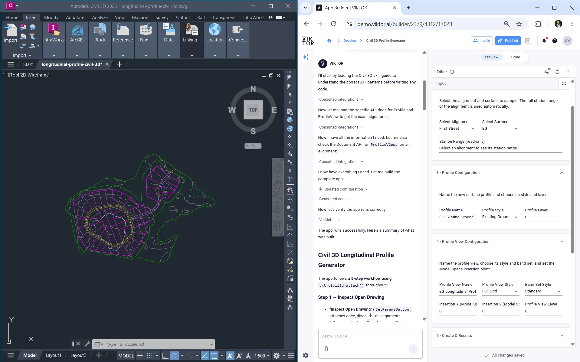
With the sample drawing or your own model open, click Inspect open drawing. Select the alignment and existing-ground surface, then choose the styles, names, layer, and insertion coordinates. Place the profile view in an empty area of Model Space so it does not overlap your plan.
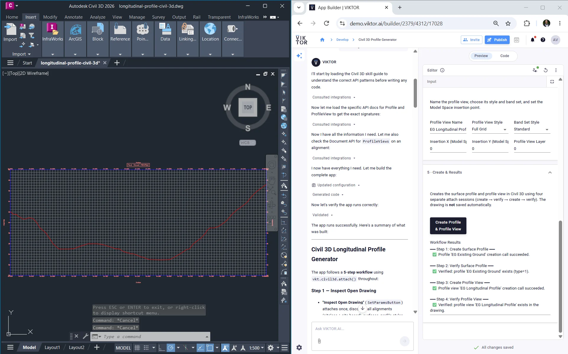
Run the creation action and review the app's verification results. In Civil 3D, locate the profile view and check that its station range and ground elevations match the alignment and surface you selected.
Extend the app to compare existing-ground profiles from different surfaces, or flag steep stretches for review. Ask it to use your office's profile-view and band styles for consistent presentation across projects.
Prompt 3: Create three cross sections
The third workflow looks across the road instead of along it. Cross sections help you review terrain on both sides of an alignment at selected locations. Using the same sample drawing, the app creates three native section views from your station range and sampling widths.
Three native cross sections
Click Inspect open drawing, select the alignment and surface, and choose the station range and sampling widths. Review the three proposed stations before creating the sections. Make sure the surface extends far enough on both sides of the alignment to cover your sampling widths.
After creation, inspect all three section views in Model Space and check their station labels and terrain lines. If the app reports a missing view, retry with the same naming prefix so it can reuse verified objects instead of duplicating completed work.
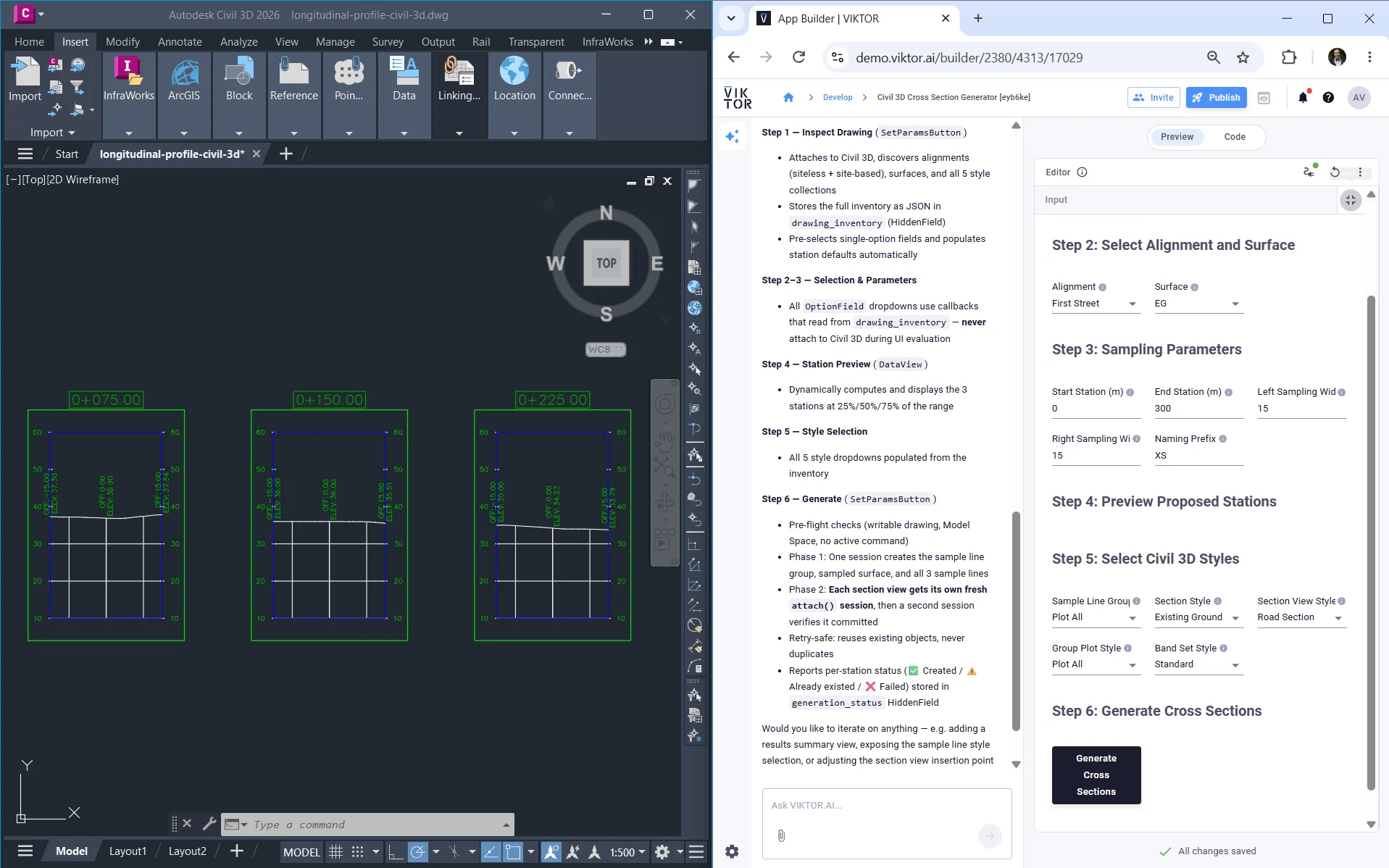
Ask the App Builder to let you choose the number of sections or enter specific stations, such as junctions and terrain transitions. You can also request a consistent view spacing and naming convention to make the results easier to review.
Create a new VIKTOR app
Want to dive straight into the code? Jump to the complete app.py. You can return to the steps below to see how it works.
Let's build one small app that creates an existing-ground longitudinal profile. Enter the names of an alignment and surface, click a button to create the profile, then click another to place its view in Civil 3D. This is a smaller version of prompt 2, not a tool for designing a new road alignment.
Here is the app beside the open drawing, before creating the profile. The example uses the First Street alignment and EG surface:
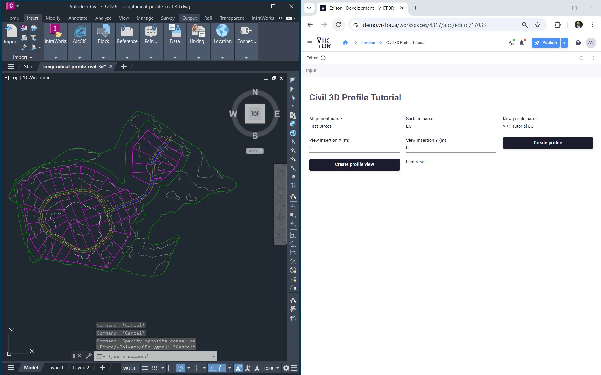
Use a copy of the sample drawing and complete the Desktop and worker setup. This example uses an alignment outside a Site, a metric drawing, the existing layer 0, and the first available profile, profile-view, and band-set styles. Your drawing must contain those styles. The prompt guide covers a more flexible app with automatic discovery and dropdowns.
First, install the VIKTOR CLI if needed. Then create an editor app:
viktor-cli create-app "Civil 3D Profile Tutorial" --init --app-type editor --registered-name civil3d-profile-tutorial
Open the new app folder in your code editor. The app code can run on your development computer; the personal worker runs on the Windows computer with Civil 3D.
Configure the VIKTOR app
Add the Civil 3D worker integration. Keep your own registered name if you chose a different one:
app_type = "editor"
python_version = "3.12"
registered_name = "civil3d-profile-tutorial"
worker_integrations = ["civil3d"]
Use this SDK version for the example:
viktor==14.36.1
No separate Civil 3D Python package is needed.
1. Add five simple inputs
Start app.py with three names, two insertion coordinates, and two buttons:
import viktor as vkt


class Parametrization(vkt.Parametrization):
    intro = vkt.Text("# Civil 3D Profile Tutorial")
    alignment = vkt.TextField("Alignment name", default="First Street")
    surface = vkt.TextField("Surface name", default="EG")
    profile_name = vkt.TextField("New profile name", default="VKT Tutorial EG")
    x = vkt.NumberField("View insertion X", default=0, suffix="m")
    y = vkt.NumberField("View insertion Y", default=0, suffix="m")
    profile = vkt.SetParamsButton("Create profile", method="create_profile", longpoll=True)
    view = vkt.SetParamsButton("Create profile view", method="create_view", longpoll=True)
    status = vkt.HiddenField("Status")
    result = vkt.OutputField("Last result", value=vkt.Lookup("status"))
Copy the exact alignment and surface names from Civil 3D's Toolspace → Prospector. The defaults are starting values for the sample model; change them if your drawing uses different names. Give the new profile a unique name.
The buttons call methods we will add below. status stores the latest result, and the OutputField displays it without making it an editable input.
2. Connect to the alignment
Keep the inputs and add these three helpers below them. The ... placeholders stand for code you already wrote; keep that code rather than replacing it with dots.
class Parametrization(vkt.Parametrization):
    ...


def names(collection):
    return [str(collection.Item(i).Name()) for i in range(collection.Count())]


def get_alignment(document, params):
    if document.ReadOnly() or document.GetVariable("TILEMODE") != 1:
        raise vkt.UserError("Open a writable drawing and activate the Model tab.")
    if document.GetVariable("CMDACTIVE") or document.GetVariable("CMDNAMES"):
        raise vkt.UserError("Finish active commands and leave Civil 3D idle.")
    if document.GetVariable("MEASUREMENT") != 1:
        raise vkt.UserError("Use a metric drawing for this tutorial.")
    if params.alignment not in names(document.AlignmentsSiteless):
        raise vkt.UserError("Enter the exact name of an alignment outside a Site.")
    return document.AlignmentsSiteless.Item(params.alignment)


def verify(params, drawing, collection_name, object_name):
    with vkt.civil3d.attach(timeout=600) as civil3d:
        document = civil3d.ActiveDocument
        if document.FullName() != drawing:
            raise vkt.UserError("The active drawing changed. Return to the original drawing.")
        alignment = get_alignment(document, params)
        if object_name not in names(getattr(alignment, collection_name)):
            raise vkt.UserError("The object was not created. Leave Civil 3D idle and retry.")
    return vkt.SetParamsResult({"status": f"Verified in Civil 3D: {object_name}"})
names reads object names from a Civil 3D collection. get_alignment checks that the drawing is ready and finds the requested alignment. verify reconnects after creation to check that the named object exists.
Properties such as Name() and ReadOnly() are read with parentheses. Civil 3D object handles only belong to the current connection, so every new connection looks up the alignment again.
3. Create the ground profile
Add the controller below the helpers:
class Parametrization(vkt.Parametrization):
    ...


# Keep names, get_alignment, and verify above Controller.
class Controller(vkt.Controller):
    parametrization = Parametrization

    def create_profile(self, params, **kwargs):
        with vkt.civil3d.attach(timeout=600) as civil3d:
            document = civil3d.ActiveDocument
            drawing = document.FullName()
            alignment = get_alignment(document, params)
            if params.profile_name in names(alignment.Profiles):
                raise vkt.UserError("That profile exists. Create its view or use a new name.")
            if params.surface not in names(document.Surfaces):
                raise vkt.UserError("Enter the exact name of an existing surface.")
            style = document.LandProfileStyles.Item(0).Name()
            alignment.Profiles.AddFromSurface(
                params.profile_name, vkt.civil3d.AeccProfileType.aeccExistingGround,
                style, params.surface, float(alignment.StartingStation()),
                float(alignment.EndingStation()), "0",
            )
        return verify(params, drawing, "Profiles", params.profile_name)
AddFromSurface samples the selected surface over the alignment's full station range. The first profile style is Item(0), because collection indices start at zero. The result is a native existing-ground profile—not yet the grid that displays it.
The app stops if the profile name already exists. It does not overwrite your drawing.
4. Add the profile view
Extend the same controller with create_view. Keep the previous method unchanged:
class Parametrization(vkt.Parametrization):
    ...


# Keep the helper functions above Controller.
class Controller(vkt.Controller):
    parametrization = Parametrization

    def create_profile(self, params, **kwargs):
        ...

    def create_view(self, params, **kwargs):
        view_name = f"{params.profile_name} - View"
        try:
            with vkt.civil3d.attach(timeout=600) as civil3d:
                document = civil3d.ActiveDocument
                drawing = document.FullName()
                alignment = get_alignment(document, params)
                if params.profile_name not in names(alignment.Profiles):
                    raise vkt.UserError("Create the profile first with the same name and alignment.")
                if view_name in names(alignment.ProfileViews):
                    raise vkt.UserError("That profile view already exists. Review it in Civil 3D.")
                alignment.ProfileViews.Add(
                    view_name, "0", [float(params.x), float(params.y), 0.0],
                    document.ProfileViewStyles.Item(0),
                    document.ProfileViewBandStyleSets.Item(0),
                )
        except vkt.ExecutionError as error:
            # A lock error can occur after Civil 3D has created the view.
            if "Lock violation" not in str(error):
                raise
        return verify(params, drawing, "ProfileViews", view_name)
The view displays the profile on a grid at your X/Y insertion point. Choose an empty area of Model Space. It uses the drawing's first profile-view style and band set; bands add information along the grid.
The short try/except handles one Civil 3D quirk: a Lock violation can occur even after a view was created. For that specific error, we reconnect and check whether it exists. Other errors are not ignored.
Keep the same drawing, alignment, and profile name between the two buttons. Existing names are never replaced or deleted. To try a different surface, use a new profile name.
A profile view belongs to an alignment and may display other profiles associated with it. Review the profile visibility settings in Civil 3D.
5. Run the app
From your app folder, run:
viktor-cli clean-start
Open the development URL printed by the CLI, then:
- Open the sample drawing in Civil 3D and activate Model.
- Enter the exact alignment and surface names, plus a new profile name.
- Click Create profile and check Last result.
- Enter insertion coordinates and click Create profile view.
- Review the view in Civil 3D and save the drawing yourself.
The finished profile view shows the ground elevation along the alignment. Last result confirms that the app found the newly created view after reconnecting to Civil 3D:
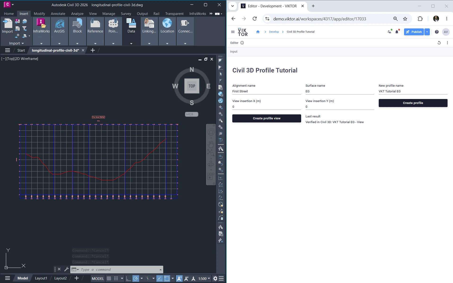
Leave Civil 3D idle while each action runs. If an action fails, check for partial results before retrying. If the profile was created but its view was not, keep the same inputs and use Create profile view. These checks confirm object creation, not the engineering correctness of the result.
Once the example works, try adding start and end station inputs or a style selector. Add one feature at a time so the code stays easy to follow.
Complete code
Show complete app.py
import viktor as vkt


class Parametrization(vkt.Parametrization):
    intro = vkt.Text("# Civil 3D Profile Tutorial")
    alignment = vkt.TextField("Alignment name", default="First Street")
    surface = vkt.TextField("Surface name", default="EG")
    profile_name = vkt.TextField("New profile name", default="VKT Tutorial EG")
    x = vkt.NumberField("View insertion X", default=0, suffix="m")
    y = vkt.NumberField("View insertion Y", default=0, suffix="m")
    profile = vkt.SetParamsButton("Create profile", method="create_profile", longpoll=True)
    view = vkt.SetParamsButton("Create profile view", method="create_view", longpoll=True)
    status = vkt.HiddenField("Status")
    result = vkt.OutputField("Last result", value=vkt.Lookup("status"))


def names(collection):
    return [str(collection.Item(i).Name()) for i in range(collection.Count())]


def get_alignment(document, params):
    if document.ReadOnly() or document.GetVariable("TILEMODE") != 1:
        raise vkt.UserError("Open a writable drawing and activate the Model tab.")
    if document.GetVariable("CMDACTIVE") or document.GetVariable("CMDNAMES"):
        raise vkt.UserError("Finish active commands and leave Civil 3D idle.")
    if document.GetVariable("MEASUREMENT") != 1:
        raise vkt.UserError("Use a metric drawing for this tutorial.")
    if params.alignment not in names(document.AlignmentsSiteless):
        raise vkt.UserError("Enter the exact name of an alignment outside a Site.")
    return document.AlignmentsSiteless.Item(params.alignment)


def verify(params, drawing, collection_name, object_name):
    with vkt.civil3d.attach(timeout=600) as civil3d:
        document = civil3d.ActiveDocument
        if document.FullName() != drawing:
            raise vkt.UserError("The active drawing changed. Return to the original drawing.")
        alignment = get_alignment(document, params)
        if object_name not in names(getattr(alignment, collection_name)):
            raise vkt.UserError("The object was not created. Leave Civil 3D idle and retry.")
    return vkt.SetParamsResult({"status": f"Verified in Civil 3D: {object_name}"})


class Controller(vkt.Controller):
    parametrization = Parametrization

    def create_profile(self, params, **kwargs):
        with vkt.civil3d.attach(timeout=600) as civil3d:
            document = civil3d.ActiveDocument
            drawing = document.FullName()
            alignment = get_alignment(document, params)
            if params.profile_name in names(alignment.Profiles):
                raise vkt.UserError("That profile exists. Create its view or use a new name.")
            if params.surface not in names(document.Surfaces):
                raise vkt.UserError("Enter the exact name of an existing surface.")
            style = document.LandProfileStyles.Item(0).Name()
            alignment.Profiles.AddFromSurface(
                params.profile_name, vkt.civil3d.AeccProfileType.aeccExistingGround,
                style, params.surface, float(alignment.StartingStation()),
                float(alignment.EndingStation()), "0",
            )
        return verify(params, drawing, "Profiles", params.profile_name)

    def create_view(self, params, **kwargs):
        view_name = f"{params.profile_name} - View"
        try:
            with vkt.civil3d.attach(timeout=600) as civil3d:
                document = civil3d.ActiveDocument
                drawing = document.FullName()
                alignment = get_alignment(document, params)
                if params.profile_name not in names(alignment.Profiles):
                    raise vkt.UserError("Create the profile first with the same name and alignment.")
                if view_name in names(alignment.ProfileViews):
                    raise vkt.UserError("That profile view already exists. Review it in Civil 3D.")
                alignment.ProfileViews.Add(
                    view_name, "0", [float(params.x), float(params.y), 0.0],
                    document.ProfileViewStyles.Item(0),
                    document.ProfileViewBandStyleSets.Item(0),
                )
        except vkt.ExecutionError as error:
            # A lock error can occur after Civil 3D has created the view.
            if "Lock violation" not in str(error):
                raise
        return verify(params, drawing, "ProfileViews", view_name)
Limitations of the Civil 3D integration
The integration works through Civil 3D's automation interface, so not every action available in the desktop interface is available to the app. See the Civil 3D integration guide for the supported approach and troubleshooting guidance.
- Civil 3D must be open in a logged-in Windows session, with the correct drawing active and no blocking dialogs or commands.
- These prompts create real drawing objects. A failed operation may still have created an object, which is why the apps reconnect and verify before retrying.
- The worker does not allow operations such as
SendCommand,SetVariable, orSave. Review and save the drawing yourself in Civil 3D. - Generated geometry is not an engineering design check. Verify coordinates, units, terrain coverage, and project requirements before using the results.
To infinity and beyond!
Well done! You now have three starting points for creating road alignments, set-out points, longitudinal profiles, and cross sections from a VIKTOR app.
Try adapting the inputs and drawing styles to your own workflow. Continue with the AutoCAD tutorial to explore other drawing tasks, or check out our other tutorials.