Tutorial - Creating and analyzing a SCIA model
Estimated time: 60 minutes

Introduction
For the section "Performing an analysis" a SCIA worker is required.
This tutorial explains how a SCIA model can be created within VIKTOR, which can be used for analysis using an external coupling. The SCIA model that we will be constructing consists of a foundation slab with piles.
Download the starting app to your hard disk. From within the app folder run the following command to install and start the app:
viktor-cli clean-start
In the browser, click the "Example" entity to open its editor and verify the app is installed and running as expected.
Folder structure
The app has the following folder structure:
scia-tutorial
├── app.py
├── model.esa
├── requirements.txt
└── viktor.config.toml
The example template SCIA file (model.esa) in this tutorial has been made in SCIA 19.0. The file cannot be opened nor run with versions < 19.0 (and is not guaranteed to work for > 19.0).
If you are using a version of SCIA other than 19.0, a template file must be created for (and the worker must run) this specific version. This can be done with the following procedure:
- Open a new project in your SCIA version of choice
- Make sure that the material that will be used is present in the materials library
- Setup the XML I/O document to export the desired results (see the SCIA documentation)
- Save the empty file as model.esa
- Replace the existing esa file with the just created one in the foundation folder
Open app.py and have a look at the code that we have set up for you. Note that the code already creates an empty SCIA
model and some basic class structure. We will extend the code and add specific SCIA objects, step-by-step, throughout
this tutorial.
Creating the corner nodes
If we assume that one of the corner points is located in the origin, the other three corner point locations can easily
be calculated using width_x and width_y. Open app.py and add the following code create_scia_model:
def create_scia_model(self, params) -> SciaModel:
    model = SciaModel()

    '''
    STRUCTURE
    '''
    # create nodes at the slab corners
    width_x = params.geometry.slab.width_x * 1e-03
    width_y = params.geometry.slab.width_y * 1e-03
    n1 = model.create_node('n1', 0, 0, 0)  # origin
    n2 = model.create_node('n2', 0, width_y, 0)
    n3 = model.create_node('n3', width_x, width_y, 0)
    n4 = model.create_node('n4', width_x, 0, 0)

    return model
The corner nodes are defined in clockwise direction, since this order will be used later to create a 3D extrusion object.
While setting up a SCIA model in VIKTOR, the 3D visualization is a very helpful feature to verify that the written
logic does indeed create the model as desired. Therefore, we will extend create_visualization_geometries to get and
show the just created nodes. This can easily be done by calling the nodes attribute of the SciaModel:
...
from viktor import Color
from viktor.geometry import Point, Sphere, Material


def create_visualization_geometries(self, params, scia_model):
    geometries = []
    for node in scia_model.nodes:
        node_obj = Sphere(Point(node.x, node.y, node.z),  params.geometry.slab.width_y * 1e-05)
        node_obj.material = Material('node', color=Color(0, 255, 0))
        geometries.append(node_obj)

    return geometries
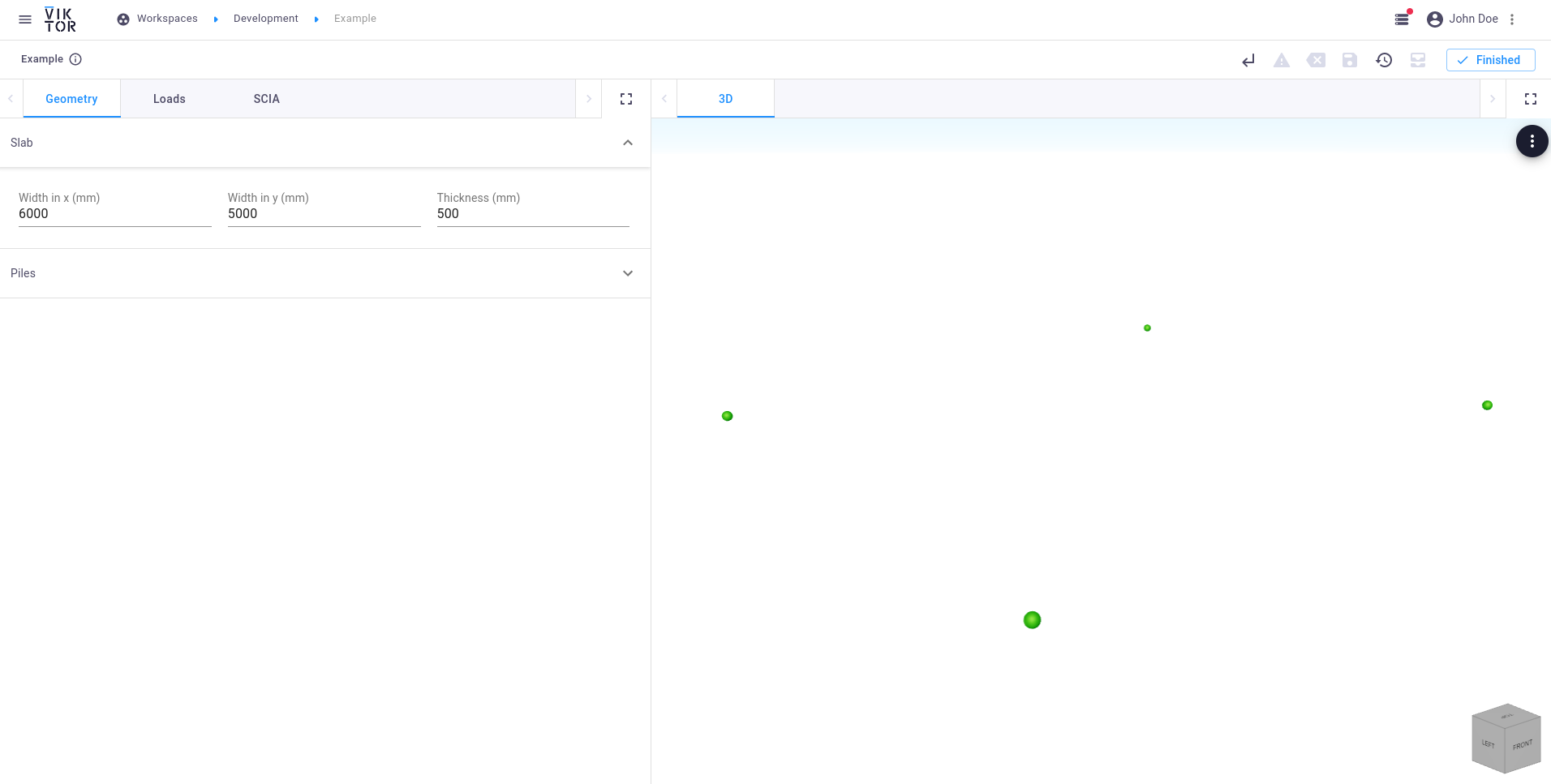 Corner nodes
Creating the piles
For the purpose of this tutorial, some parameters like the number of piles and the distance between the piles and the edge are fixed. The locations of these piles however, depend on the dimensions of the slab:
...
import numpy as np
import itertools


def create_scia_model(self, params) -> SciaModel:
    ...

    # create the pile nodes
    number_of_piles_x = 4
    number_of_piles_y = 3
    pile_edge_distance = 0.3
    pile_length = params.geometry.piles.length

    start_x = pile_edge_distance
    end_x = width_x - pile_edge_distance
    x = np.linspace(start_x, end_x, number_of_piles_x)
    start_y = pile_edge_distance
    end_y = width_y - pile_edge_distance
    y = np.linspace(start_y, end_y, number_of_piles_y)
    pile_positions = np.array(list(itertools.product(x, y)))

    pile_top_nodes = []
    pile_bottom_nodes = []
    for pile_id, (pile_x, pile_y) in enumerate(pile_positions, 1):
        n_top = model.create_node(f'K:p{pile_id}_t', pile_x, pile_y, 0)
        n_bottom = model.create_node(f'K:p{pile_id}_b', pile_x, pile_y, -pile_length)
        pile_top_nodes.append(n_top)
        pile_bottom_nodes.append(n_bottom)

    return model
Since we already loop through all the nodes in the create_visualization_geometries method
(for node in scia_model.nodes:), the nodes located at the pile ends will automatically be visualized when the app is
(automatically) restarted.
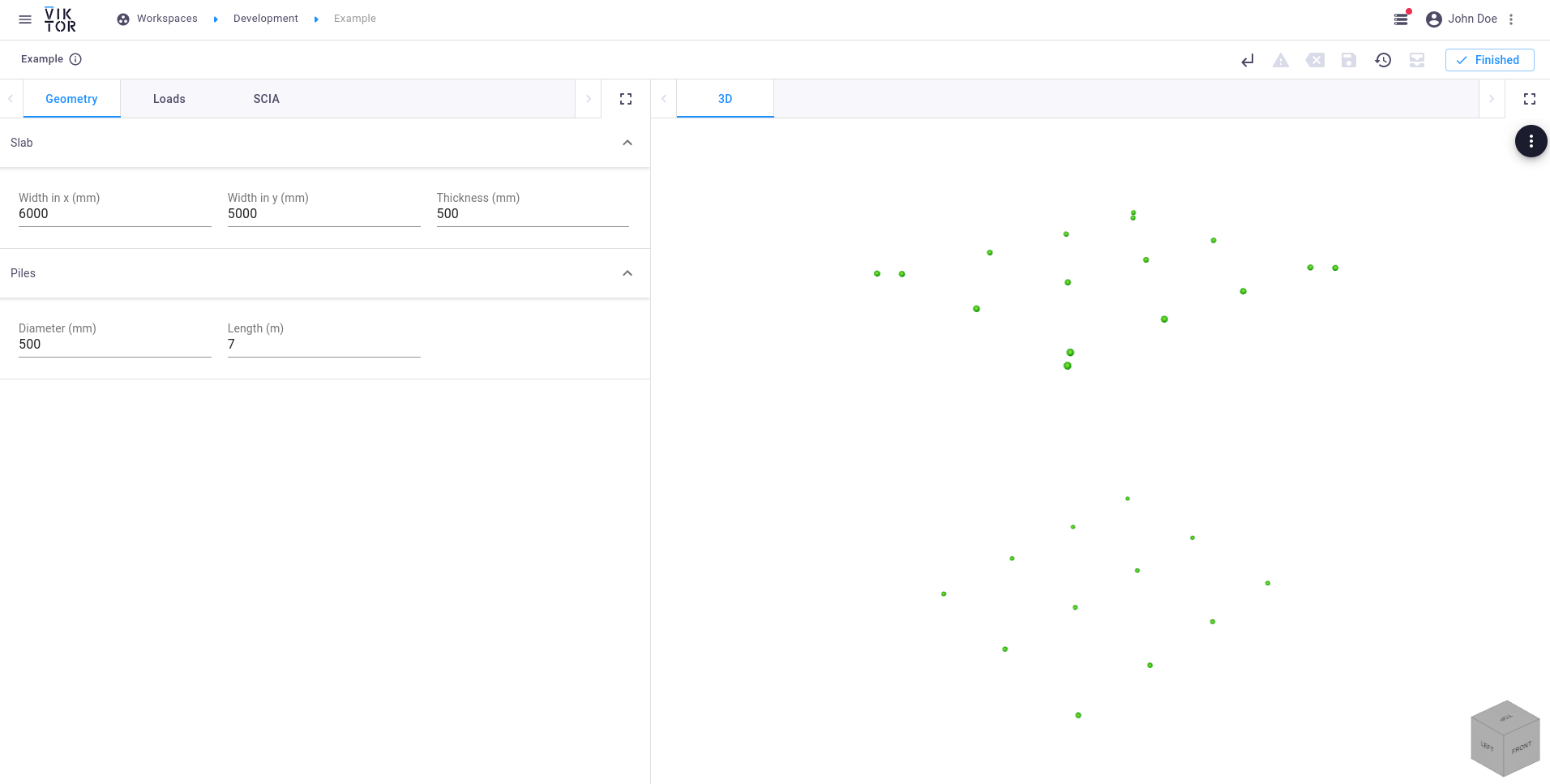 Pile nodes
The top and bottom nodes of the piles can now be used along with the pile diameter defined in the Parametrization to
create a circular cross-section and beam elements. The cross-section in turn needs a SciaMaterial as input, which
needs to be defined in the .esa model that is used.
The Material from the SCIA package is imported with a different name to prevent conflicts with the Material import
from viktor.geometry.
...
from viktor.external.scia import Material as SciaMaterial


def create_scia_model(self, params) -> SciaModel:
    ...

    # create pile beams
    pile_diameter = params.geometry.piles.diameter * 1e-03
    material = SciaMaterial(0, 'C30/37')
    cross_section = model.create_circular_cross_section('concrete_pile', material, pile_diameter)
    pile_beams = []
    for pile_id, (n_top, n_bottom) in enumerate(zip(pile_top_nodes, pile_bottom_nodes), 1):
        pile_beam = model.create_beam(n_top, n_bottom, cross_section)
        pile_beams.append(pile_beam)

    return model
For the visualization of the piles, a
CircularExtrusion is used. This object needs a diameter and
Line object which specifies the direction of the beam in terms of a start and end
Point.
...
from viktor.geometry import CircularExtrusion, Line


def create_visualization_geometries(self, params, scia_model):
    ...

   # pile beams
    pile_diameter = params.geometry.piles.diameter * 1e-03
    for beam in scia_model.beams:
        point_top = Point(beam.begin_node.x, beam.begin_node.y, beam.begin_node.z)
        point_bottom = Point(beam.end_node.x, beam.end_node.y, beam.end_node.z)
        beam_obj = CircularExtrusion(pile_diameter, Line(point_top, point_bottom))
        beam_obj.material = Material('beam', roughness=1, opacity=0.3)
        geometries.append(beam_obj)

    ...
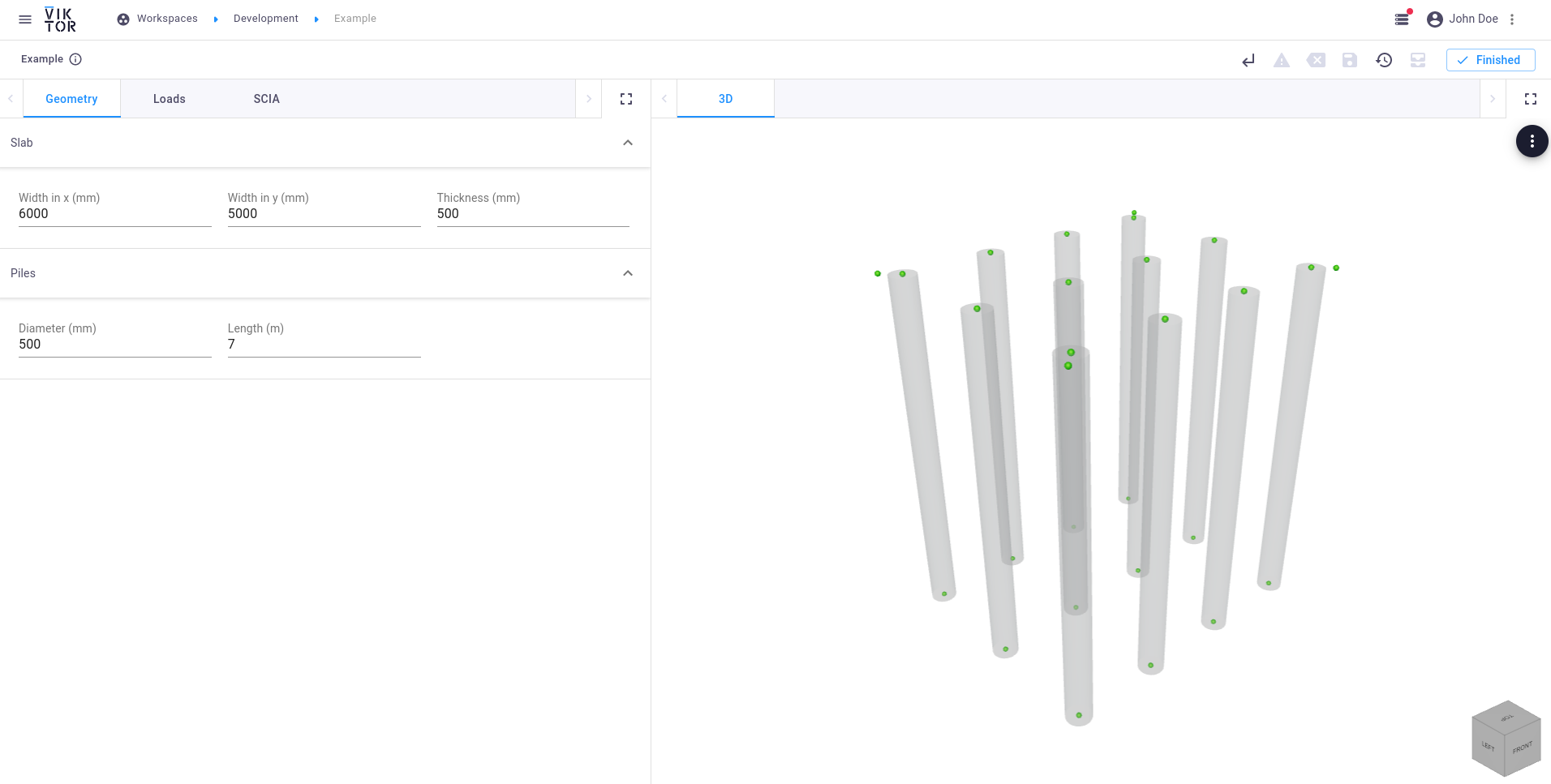 Pile beams
Creating the slab
The corner nodes that were created earlier can be used to create the concrete slab object. Extend the
create_scia_model method with the following lines:
...
from viktor.external.scia import Plane


def create_scia_model(self, params) -> SciaModel:
    ...

    # create the concrete slab
    material = SciaMaterial(0, 'concrete_slab')
    thickness = params.geometry.slab.thickness * 1e-03
    corner_nodes = [n1, n2, n3, n4]
    slab = model.create_plane(corner_nodes, thickness, name='foundation slab', material=material)

    return model
Again we can verify the position and dimensions of the created slab by means of visualization:
...
from viktor.geometry import Extrusion


def create_visualization_geometries(self, params, scia_model):
    ...

    corner_points = [
        Point(scia_model.nodes[0].x, scia_model.nodes[0].y, scia_model.nodes[0].z),
        Point(scia_model.nodes[1].x, scia_model.nodes[1].y, scia_model.nodes[1].z),
        Point(scia_model.nodes[2].x, scia_model.nodes[2].y, scia_model.nodes[2].z),
        Point(scia_model.nodes[3].x, scia_model.nodes[3].y, scia_model.nodes[3].z),
        Point(scia_model.nodes[0].x, scia_model.nodes[0].y, scia_model.nodes[0].z)
    ]

    thickness = params.geometry.slab.thickness * 1e-03
    slab_obj = Extrusion(corner_points, Line(Point(0, 0, -thickness/2), Point(0, 0, thickness/2)))
    slab_obj.material = Material('slab', roughness=1, opacity=0.3)
    geometries.append(slab_obj)

    ...
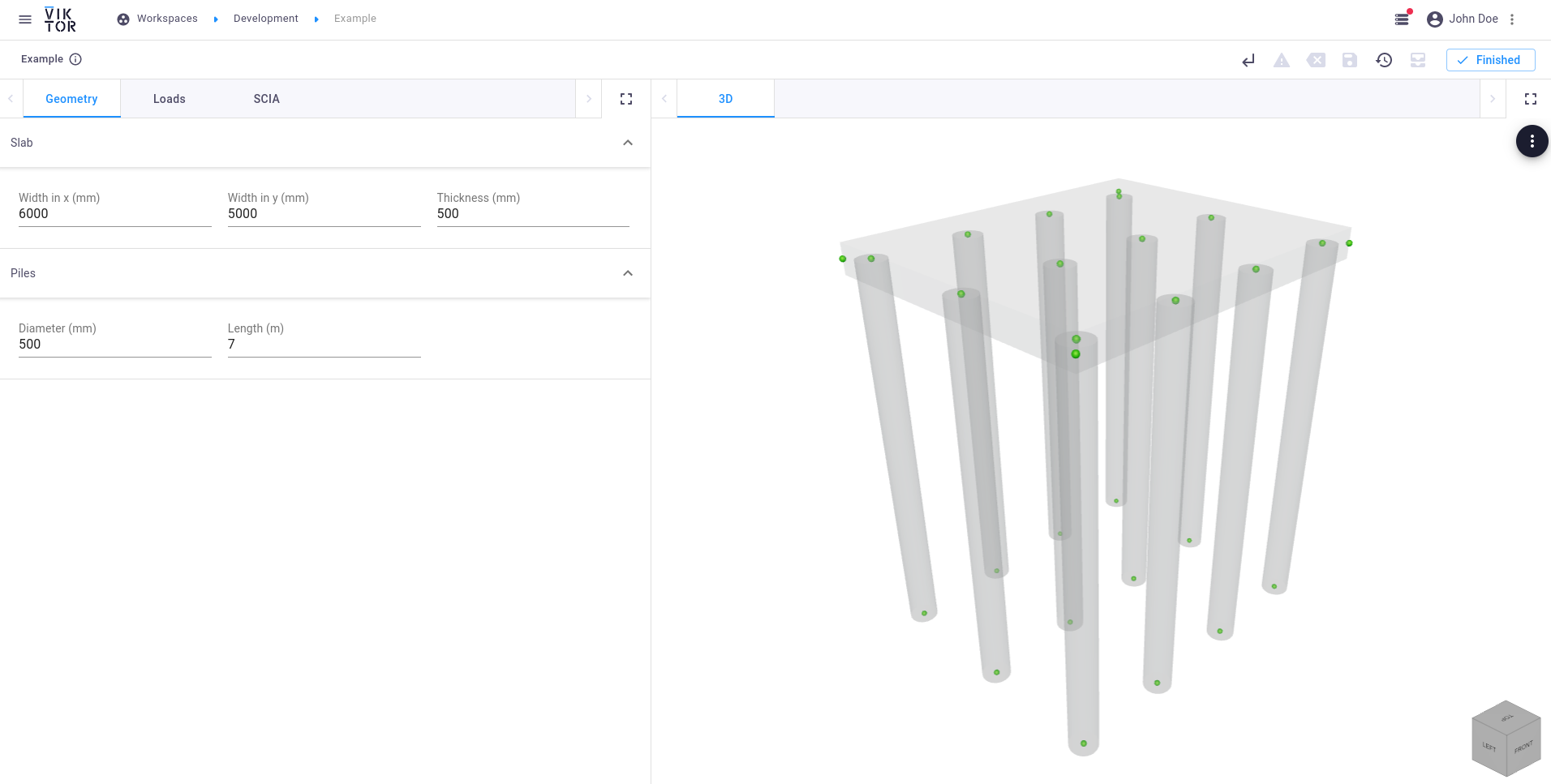 Slab
Slab
Creating the supports
Since the foundation will be completely underground, the following supports have to be attached:
-
Point supports (
PointSupport) at the bottom of each pile:...
from viktor.external.scia import PointSupport
def create_scia_model(self, params) -> SciaModel:
...
'''
SUPPORTS
'''
# create pile point supports
freedom_v = (
PointSupport.Freedom.FREE, PointSupport.Freedom.FREE, PointSupport.Freedom.FLEXIBLE,
PointSupport.Freedom.FREE, PointSupport.Freedom.FREE, PointSupport.Freedom.FREE
)
kv = 400 * 1e06
stiffness_v = (0, 0, kv, 0, 0, 0)
for pile_id, pile_beam in enumerate(pile_beams, 1):
n_bottom = pile_beam.end_node
model.create_point_support(f'Sn:p{pile_id}', n_bottom, PointSupport.Type.STANDARD,
freedom_v, stiffness_v, PointSupport.CSys.GLOBAL)
return model -
Line supports (
LineSupport) on the piles:...
from viktor.external.scia import LineSupport
def create_scia_model(self, params) -> SciaModel:
...
# create pile line supports
kh = 10 * 1e06
for pile_id, pile_beam in enumerate(pile_beams, 1):
model.create_line_support_on_beam(pile_beam, x=LineSupport.Freedom.FLEXIBLE, stiffness_x = kh,
y=LineSupport.Freedom.FLEXIBLE, stiffness_y = kh,
z=LineSupport.Freedom.FREE, rx=LineSupport.Freedom.FREE,
ry=LineSupport.Freedom.FREE, rz=LineSupport.Freedom.FREE,
c_sys=LineSupport.CSys.GLOBAL)
return model -
Line supports (
LineSupport) on the slab edges:...
def create_scia_model(self, params) -> SciaModel:
...
# create the slab supports
stiffness_x = 50 * 1e06
stiffness_y = 50 * 1e06
for edge in (1, 3):
model.create_line_support_on_plane((slab, edge),
x=LineSupport.Freedom.FLEXIBLE, stiffness_x=stiffness_x,
y=LineSupport.Freedom.FREE,
z=LineSupport.Freedom.FREE,
rx=LineSupport.Freedom.FREE,
ry=LineSupport.Freedom.FREE,
rz=LineSupport.Freedom.FREE)
for edge in (2, 4):
model.create_line_support_on_plane((slab, edge),
x=LineSupport.Freedom.FREE,
y=LineSupport.Freedom.FLEXIBLE, stiffness_y=stiffness_y,
z=LineSupport.Freedom.FREE,
rx=LineSupport.Freedom.FREE,
ry=LineSupport.Freedom.FREE,
rz=LineSupport.Freedom.FREE)
return model
Creating the load combinations
Adding a load combination to the SCIA model is done in three steps, similarly as in the SCIA interface:
- Create a load group (
LoadGroup) - Create a load case (
LoadCase) - Create a load combination (
LoadCombination)
...
from viktor.external.scia import LoadCase, LoadCombination, LoadGroup


def create_scia_model(self, params) -> SciaModel:
    ...

    '''
    SETS
    '''
    # create the load group
    lg = model.create_load_group('LG1', LoadGroup.LoadOption.VARIABLE, LoadGroup.RelationOption.STANDARD,
                                 LoadGroup.LoadTypeOption.CAT_G)

    # create the load case
    lc = model.create_variable_load_case('LC1', 'first load case', lg, LoadCase.VariableLoadType.STATIC,
                                         LoadCase.Specification.STANDARD, LoadCase.Duration.SHORT)

    # create the load combination
    load_cases = {
        lc: 1
    }

    model.create_load_combination('C1', LoadCombination.Type.ENVELOPE_SERVICEABILITY, load_cases)

    return model
Creating the load(s)
The last component of a complete SCIA model is the actual load that is applied on the structure. In this example, a simple uniform surface load is placed on the slab:
...
from viktor.external.scia import SurfaceLoad


def create_scia_model(self, params) -> SciaModel:
    ...

    '''
    LOADS
    '''
    # create the load
    force = params.loads.input.uniform_load * 1e03
    force *= -1  # in negative Z-direction
    model.create_surface_load('SF:1', lc, slab, SurfaceLoad.Direction.Z, SurfaceLoad.Type.FORCE, force,
                              SurfaceLoad.CSys.GLOBAL, SurfaceLoad.Location.LENGTH)

    return model
Downloading the SCIA model
It is always helpful to generate the XML representation of the SCIA model and to manually load this input in the SCIA interface. This will help in verifying that, for example, all the loads are defined correctly in terms of placement and magnitude. In the app we will add a feature to download the necessary files.
In order to be able to view the created model in the SCIA interface, the following three files are needed:
- Empty SCIA model (
*.esa) - Definition file (
*.def) - Input file (
*.xml)
Now let's fill the download methods that we defined earlier in Foundation:
from pathlib import Path
...
from viktor import ..., File


class Foundation(ViktorController):
    ...

    def download_scia_input_esa(self, params, **kwargs):
        scia_input_esa = self.get_scia_input_esa()
        return DownloadResult(scia_input_esa, 'model.esa')

    def download_scia_input_xml(self, params, **kwargs):
        scia_model = self.create_scia_model(params)
        input_xml, _ = scia_model.generate_xml_input()

        return DownloadResult(input_xml, 'test.xml')

    def download_scia_input_def(self, params, **kwargs):
        m = SciaModel()
        _, input_def = m.generate_xml_input()
        return DownloadResult(input_def, 'viktor.xml.def')

    def get_scia_input_esa(self) -> File:
        return File.from_path(Path(__file__).parent / 'model.esa')
pathlib's Path object is VIKTOR's recommended way of defining a path.
You can now download the files from within VIKTOR.
Viewing the model in SCIA
SCIA 19.0 is required if using the example file.
When the files are obtained, the empty .esa model can be opened in SCIA. This model will now be updated with the created input .xml file. In SCIA Engineer:
- Click on
File->Update->XML file - Select the
test.xmlfile
It is important that the .xml and the .def files are located in the same directory, and the filename of the .def should not be changed. If this name is changed, make sure to also change the reference to this .def file in the input .xml file.
The updated SCIA model should look like this:
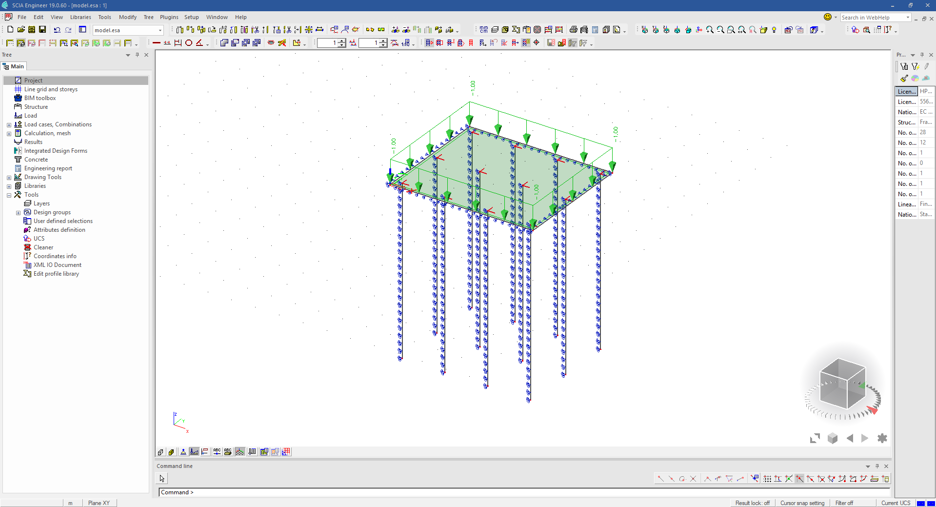 SCIA model generated by VIKTOR
Performing an analysis
This step requires a SCIA worker.
The three files that are used for the verification above, can now be used as input for the external analysis.
An I/O document has to be defined in the .esa file, which has to be named "output". If not defined, the worker will
not be able to write this expected document and fails to execute.
In this example, the empty model.esa has the following structure of the I/O document:
 I/O document of the esa model
Let's create a second view, which is a combination of geometry and data (results). Set the duration of this view to 60 seconds, which indicates that it concerns a long-running job with a manual update button. This button will be connected to the SCIA analysis:
...
from viktor.external.scia import SciaAnalysis
from viktor.views import DataGroup, GeometryAndDataView, GeometryAndDataResult


class Foundation(ViktorController):
    ...

    @GeometryAndDataView("SCIA result", duration_guess=60, x_axis_to_right=True)
    def run_scia(self, params, **kwargs):
        scia_model = self.create_scia_model(params)

        # create input files
        input_xml, input_def = scia_model.generate_xml_input()
        input_esa = self.get_scia_input_esa()

        # analyze SCIA model
        scia_analysis = SciaAnalysis(input_xml, input_def, input_esa)
        scia_analysis.execute(300)  # timeout after 5 minutes

        data_result = DataGroup()
        geometries = self.create_visualization_geometries(params, scia_model)
        return GeometryAndDataResult(geometries, data_result)
After execution, the result can easily be called and parsed as desired.
The "Reactions" results (defined in the I/O document) of the load combination C1 can be parsed from the analysis result using the provided output parser as is shown in the snippet below:
...
from viktor.external.scia import OutputFileParser
from viktor.views import DataItem


class Foundation(ViktorController):
    ...

    @GeometryAndDataView(...)
    def run_scia(self, params, **kwargs):
        scia_model = self.create_scia_model(params)

        # create input files
        input_xml, input_def = scia_model.generate_xml_input()
        input_esa = self.get_scia_input_esa()

        # analyze SCIA model
        scia_analysis = SciaAnalysis(input_xml, input_def, input_esa)
        scia_analysis.execute(300)  # timeout after 5 minutes
        scia_result = scia_analysis.get_xml_output_file()

        # parse analysis result
        result = OutputFileParser.get_result(scia_result, "Reactions", parent='Combinations - C1')
        reactions = result['Nodal reactions']

        max_rz = float(max(reactions['R_z']))
        data_result = DataGroup(
            DataItem('SCIA results', ' ', subgroup=DataGroup(
                DataItem('Maximum pile reaction', max_rz, suffix='N', number_of_decimals=2)
            ))
        )

        geometries = self.create_visualization_geometries(params, scia_model)
        return GeometryAndDataResult(geometries, data_result)
The pile reactions as seen from within the SCIA interface show a maximum of 3.3 kN (depending on your load input):
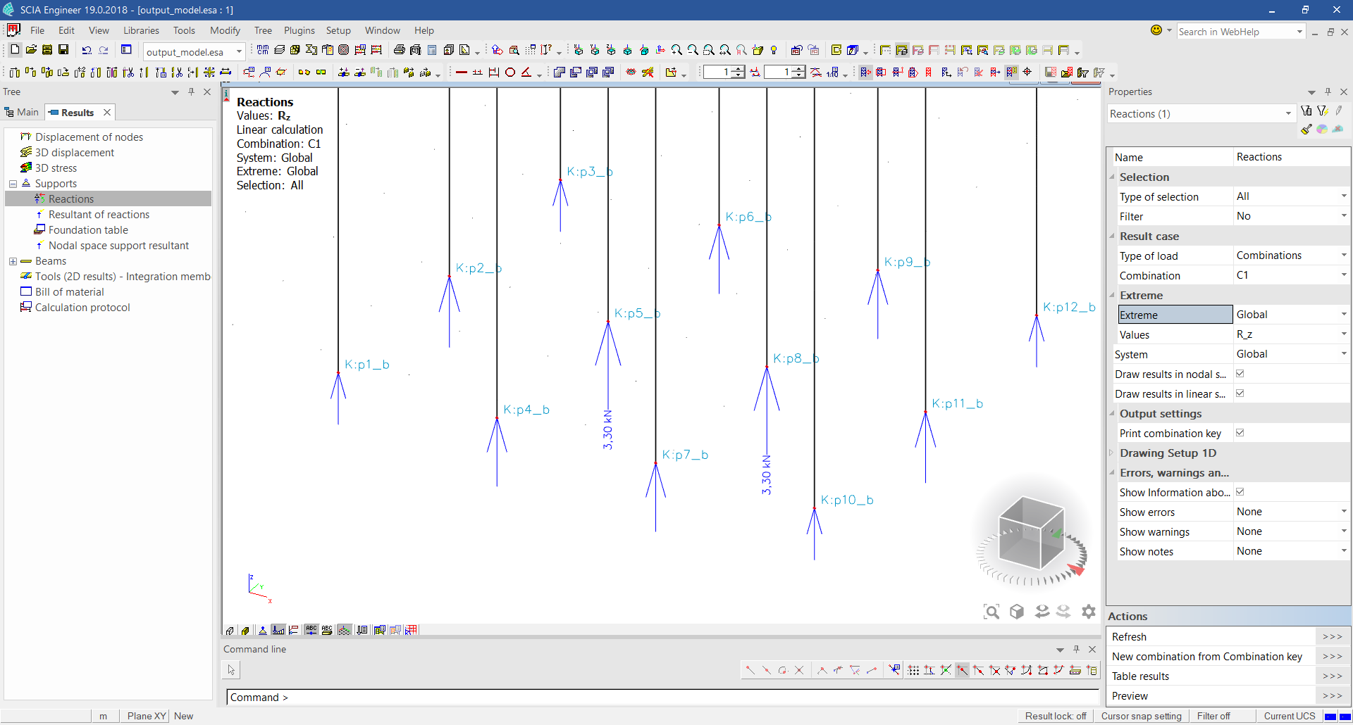 SCIA analysis result in SCIA
From the result obtained in VIKTOR we can validate that we indeed obtained the maximum reaction force of this load combination:
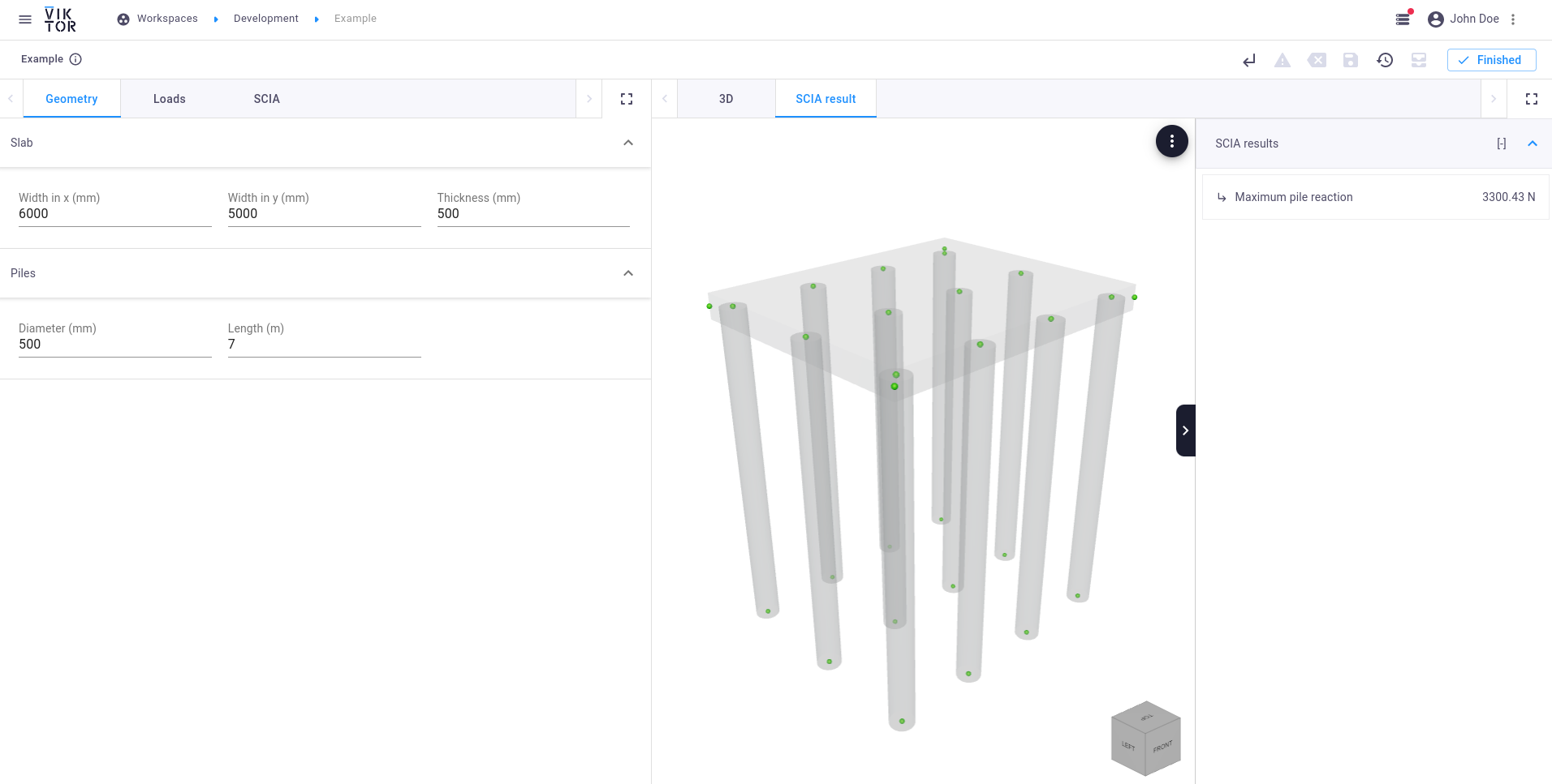 SCIA analysis result obtained in VIKTOR